


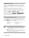
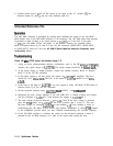
BNC CABLE
FREQUENCY COUNTER
TEST CABLE
A
15’J
10
1
Al&J100
Jl
sm624e
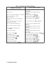
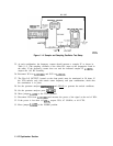
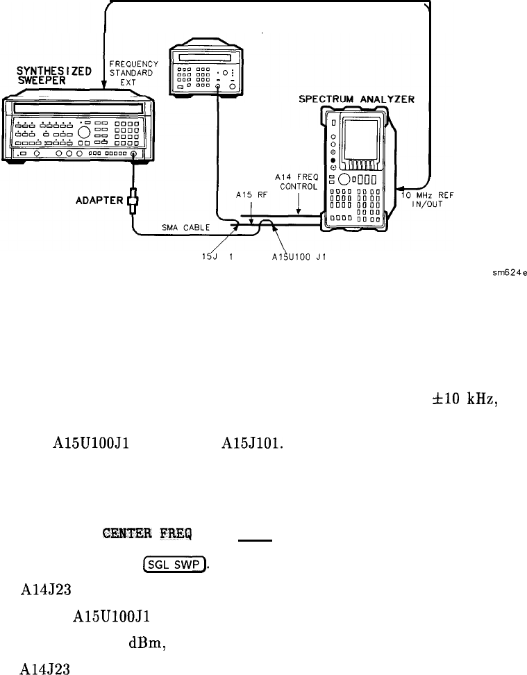
Figure 1 l-4. Sampler and Sampling Oscillator Test Setup
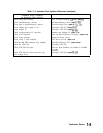
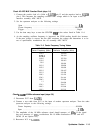
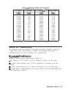
25. At each combination, the frequency counter should measure a sampler IF as shown in
Table 11-5. (The sampling oscillator of the offset PLL tunes to the frequencies listed in
the table.) If the frequency counter does not read the indicated sampler IF
f10
kHz,
suspect the Al5 RF assembly.
26. Reconnect W34 to A15UlOOJl and W32 to
A15JlOl.
27. The First LO OUTPUT, located on the front panel, must be terminated in 50 ohms. If
the YTO unlocks only with certain center frequency and span combinations, check that
the termination is in place.
28. Set the spectrum analyzer
C3MTEE
FREq and (SPAN) to generate the unlock conditions.
29. On the spectrum analyzer press
(SGLSWP).
30. Move jumper A14J23 to the TEST position.
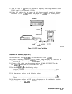
31. Disconnect W34 from A15UlOOJl and measure the power of the signal at the end of W34.
32. If the power is less than -6.5
dBm,
suspect W34, A7 SLODA, or All YTO.
33. Move jumper A14J23 to the NORM position.
1 I-12 Synthesizer Section