


Narrow 10 kHz resolution bandwidth: Check for printed-circuit board contamination. Clean
the board as required.
IF Gain Compression in 10 kHz resolution bandwidth: FET transistors Q202, Q203, Q501,
and Q503 can deteriorate with age. Measuring less than 0 volts on the FET source indicates a
bad FET.
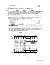
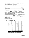
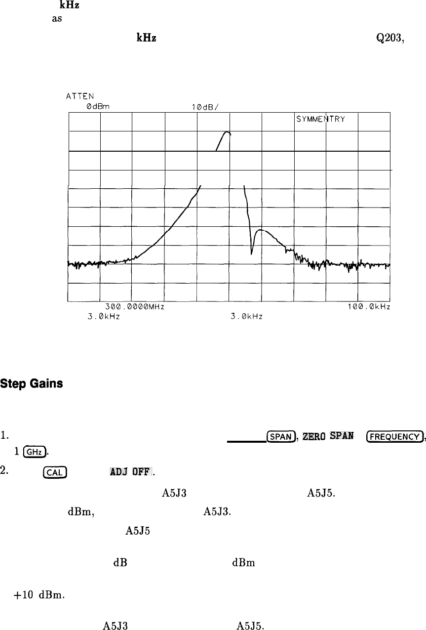
ATTEN
10dB
RL
0dBm
10dB/
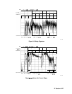
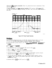
BROKEN
SYMMEbTRY
BROKEN
SYMMEbTRY
\\
\\
CENTER
300.0000MHz
CENTER
300.0000MHz
*RBW
3.0kHz
*RBW
3.0kHz
VBW
3.0kHz
VBW
3.0kHz
SPAN
100.0kHz
SPAN
100.0kHz
SWP 70msSWP 70ms
SK184
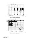
Figure 9-15. Faulty Crystal Symmetry
Step
Gains
Refer to function blocks B, H, and I of A5 IF filter schematic diagram (sheets 1 of 3 and
2 of 3) in the HP 8560 E-Series Spectrum Analyzer Component Level Information.
1.
On the HP 85623 spectrum analyzer, press (PRESET),
[SPATJ),
ZIZRO
SPAIN
,
(-1,
and
10.
2.
Press
LCAL)
and IF
BDJ
OFF.
3. Disconnect W29 (coax 7) from A5J3 and W27 (coax 3) from
A5J5.
4. Inject a -5
dBm,
10.7 MHz signal into
A5J3.
5. Monitor the output of A5J5 with another spectrum analyzer.
6. Simultaneously decrease the signal generator output and HP 85623 spectrum analyzer
reference level in 10 dB steps down to a -50
dBm
reference level.
7. At each step, the signal displayed on the other spectrum analyzer should be close to
+lO
dBm.
(More subtle IF gain problems might require smaller signal generator and
reference level steps.)
8. Reconnect W29 to A5J3 and W27 (coax 3) to
A5J5.
IF Section 9-31