


9. The measured voltage should be approximately
+5
Vdc. If the voltage is not
i-5
Vdc,
troubleshoot the Al4 frequency control assembly.
10. Connect the positive lead of a DVM to A14J18 pin 15. The voltage should measure within
f10
mV
of the Gate Bias voltage listed on the A7 label.
11. If this voltage is not within the correct range, refer to the “LO Distribution Amplifier
Adjustment” in Chapter 2, “Adjustment Procedures.”
12. If the voltage varies between 0 Vdc and -2 Vdc, adjust the Gate Bias for a DVM reading
within
f10
mV
of the Gate Bias voltage listed on the A7 label. If the voltage does not
vary between 0 Vdc and -2 Vdc, troubleshoot the Al4 Frequency Control Assembly.
13. Disconnect the jumper from A14J19 to A14JlO. Press luNE) to turn the spectrum
analyzer off. Reconnect W12 to
A14JlO.
Press
LLINE)
to turn the spectrum analyzer on.
14. If the DVM reading changes significantly, the A7 is probably defective.
A8 Low Band Mixer
1. Connect the HP 85623 CAL OUTPUT to the INPUT
500
connector.
2. Set the HP 85623 as follows:
Center frequency . . . . . . . . . . . . . . . . . . . . . . . . . . . . . . . . . . . . . . . . . . . . ...300 MHz
Span . . . . . . . . . . . . . . . . . . . . . . . . . . . . . . . . . . . . . . . . . . . . . . . . . . . . . . . . . . . . . OHz
Input attenuation . . . . . . . . . . . . . . . . . . . . . . . . . . . . . . . . . . . . . . . . . . . . . . . . . 10 dB
3. Check to see that A8 is receiving the -5 V and -4 V supply voltages from Al4 via W12.
4. Using another spectrum analyzer, check for approximately -21
dBm
(300 MHz) at the
input of A8. (This level can easily be measured at the output of FL1 by disconnecting W45
from
FLl.)
5. If the level at the input of A8 is less than -25
dBm,
suspect FL1 low-pass filter, A10
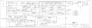
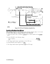
RYTHM, or A9 input attenuator. Refer to power levels shown on Figure 12-8, HP 85623
RF Section Troubleshooting Block Diagram.
6. Check for approximately -30
dBm
(3.9107 GHz) at the output of A8. (This level can
easily be measured at the output of FL2 by disconnecting W57 from FL2.)
7. If the level at the output of A8 is less than -35
dBm,
suspect A8 low band mixer or FL2
low-pass filter.
RF Section 12-7