


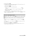
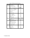
Phase Noise Problems
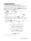
Phase Noise in Locked versus Unlocked Spans
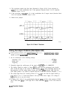
Reference versus Reference PLL Phase Noise
Fractional N versus Offset PLL or YTO PLL Phase Noise
Fractional N PLL Phase Noise
Sampler and Sampler IF
Sweep Generator Circuit
A21 OCXO
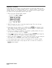
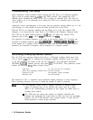
Caution
All of the assemblies are extremely sensitive to electrostatic discharge (ESD).
For further information regarding electrostatic cautions, refer to “Electrostatic
Discharge” in Chapter 1, “General Information.”
Caution
Using an active probe, such as an HP 850248, with a spectrum analyzer is
recommended for troubleshooting the RF circuitry. If an HP 1120A active
probe is being used with a spectrum analyzer, such as the HP
8566A/B,
or
HP
8569A/B
h
aving dc coupled inputs, either set the active probe for an ac
coupled output or use a dc blocking capacitor (HP 11240B) between the active
probe and the spectrum-analyzer input. Some spectrum analyzers can be set
to ac coupled. Failure to do this can result in damage to the analyzer or the
probe.
Troubleshooting Using the TAM
Refer to Chapter 7,
“General Troubleshooting,” for information on enabling the TAM for use
with the HP 85623 Spectrum Analyzer.
When using automatic fault isolation, the TAM indicates suspected circuits that need to be
manually checked. Use Table 11-2 to locate the manual procedure.
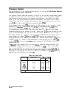
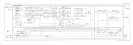
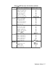
Table 11-3 lists assembly test connectors associated with each manual probe troubleshooting
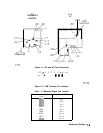
test. Figure 11-l illustrates the location of Al4 and Al5 test connectors.
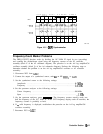
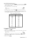
The pin locations of a 16-pin TAM connector are indicated in Figure 11-2. Table 11-l
indicates the correspondence between a measured signal line and the TAM connector pin.
11-2 Synthesizer Section