Sampler and Sampler IF
The
A15UlOO
sampler creates and mixes harmonics of the sampling oscillator with the first
LO. The resulting sampler IF (60 MHz to 96 MHz) is used to phase-lock the YTO. The
sampler IF filters unwanted products from the output of
A15UlOO
and amplifies the IF to a
level sufficient to drive the YTO loop. When the IF is between 78 and 87 MHz, PIN diodes
switch a 120 MHz notch filter in the sampler IF section.
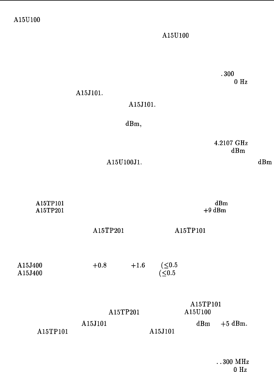
1. Set the spectrum analyzer to the following settings:
Center frequency . . . . . . . . . . . . . . . . . . . . . . . . . . . . . . . . . . . . . . . . . . . . . .300 MHz
Span . . . . . . . . . . . . . . . . . . . . . . . . . . . . . . . . . . . . . . . . . . . . . . . . . . . . . . . . . . . . OHz
2. Disconnect W32 from
A15JlOl.
3. Connect the input of a power splitter to
A15JlOl.
Connect W32 to one of the splitter
outputs. Connect the other splitter output to the input of another spectrum analyzer.
4. If a 66.7 MHz signal, greater than -15
dBm,
is not displayed on the other spectrum
analyzer, set a microwave source to the following settings:
Frequency . . . . . . . . . . . . . . . . . . . . . . . . . . . . . . . . . . . . . . . . . . . . . . . . .
4.2107GHz
Amplitude . . . . . . . . . . . . . . . . . . . . . . . . . . . . . . . . . . . . . . . . . . . . . . . . . . . . -5
dBm
5. Connect the microwave source to A15UlOOJl. A 66.7 MHz signal at approximately 0
dBm
should be displayed on the other spectrum analyzer.
6. Use an active probe/spectrum analyzer combination to measure the signal at the following
test points:
A15TPlOl
66.7 MHz, -8
dBm
A15TP201
296 MHz,
+9
dBm
7. If a correct signal is seen at A15TP201 but the signal at
A15TPlOl
is wrong, proceed as
follows:
Use an oscilloscope to measure the signals at the following test points:
A15J400 pin 1
A15J400 pin 3
+0.8
Vdc to
+1.6
Vdc (SO.5 Vp-p variation)
-0.8 Vdc to -1.6 Vdc (SO.5 Vp-p variation)
If these levels are wrong, perform the “Power and Sampler Match Adjustments” in the
sampler oscillator adjustment procedure. Refer to Chapter 2, “Adjustment Procedures.”
If adjusting the sampler match does not bring the signal at
A15TPlOl
within
specification when the signal at A15TP201 is correct, the
A15UlOO
sampler is defective.
8. The sampler IF signal at
A15JlOl
is 60 MHz to 96 MHz at -10
dBm
to
+5
dBm.
If the
signal at
A15TPlOl
is correct, but the signal at
A15JlOl
is wrong, the fault lies in the
sampler IF circuitry. Continue with the following steps.
9. Set the HP 85633 to the following settings:
Center frequency . . . . . . . . . . . . . . . . . . . . . . . . . . . . . . . . . . . . . . . . . . . .
..300MHz
Span . . . . . . . . . . . . . . . . . . . . . . . . . . . . . . . . . . . . . . . . . . . . . . . . . . . . . . . . . . . . OHz
Synthesizer Section 11-45
