


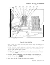

Procedure 7.
A6Al
High Voltage Assembly
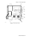
7. Place the Al7 CRT Driver assembly into the center-deck mounting slot nearest the CRT.
Use caution when routing cables to avoid damage.
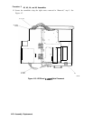
8. For Option 007 spectrum analyzers:
Place the Al6 FADC assembly into the center-deck
mounting slot nearest the left side frame. Ensure that the Al6 FADC assembly is
properly seated in the right end of the slot.
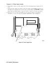
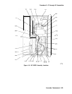
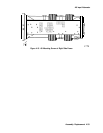
9. Secure the Al7 assembly (and Al6 assembly in Option 007) with the two
flathead
screws
removed in step 18 under “Removal.” See Figure 4-13 (2).
10. For Option 007 spectrum analyzers: Connect the two mounting posts to the left side
frame using the two screws removed in step 17 under “Removal.” See Figure 4-13 (1).
11. Fold the A2, A3, A4, and A5 assemblies into the spectrum analyzer and secure the
spectrum analyzer cover assembly as described in “Procedure 5. A2, A3, A4, and A5
Assemblies.”
Assembly Replacement 4-27