


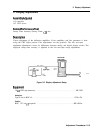
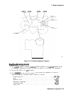
3. IF
Bandpass
Adjustment
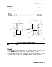
11. Move the positive DVM test lead to
A5TPl
(this is a resistor-lead type of test point).
12. Adjust A5L702 LC CTR 4 using the procedure in steps 4 through 6.
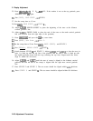
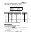
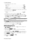
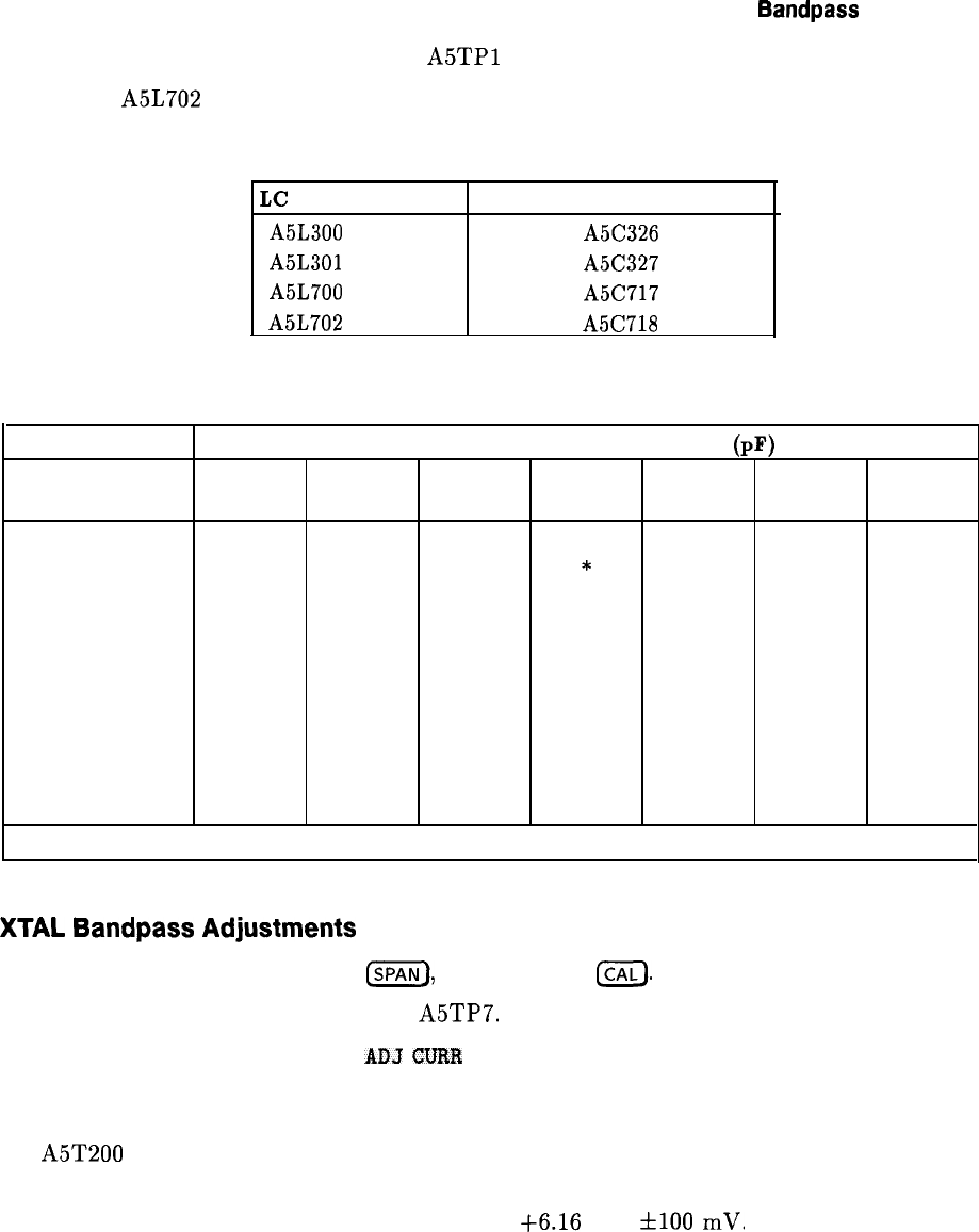
Table 2-6. Factory-Selected LC Filter Capacitors
LC
CTR Adjustment Fixed Factory Select Capacitor
A5L300
LC CTR 1
A5C326
A5L301
LC CTR 2
A5C327
A5L700
LC CTR 3
A5C717
A5L702
LC CTR 4
A5C718
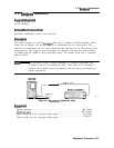
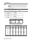
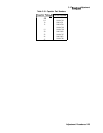
Table 2-7. LC Factory-Selected Capacitor Selection
DVM Reading (V)
Currently Loaded Capacitor Value (pF)
Replace Replace
Replace Replace
Replace
Replace Replace
6.8 with: 8.2 with:
10
with:
12
with:
15
with:
18
with:
20
with:
0 to 1.5
*
*
*
*
* *
*
1.5
to
2.5
18 18
*
* * *
*
2.5
to
3.5
15 15 18 18 * *
*
3.5
to
4.5
10 12 15 15 18 *
*
4.5
to
5.5
8.2
10 12 15 18
*
*
5.5 to 6.5
No change No change No change No change No change No change No change
6.5 to 7.5
No change No change No change No change No change No change No change
7.5
to
8.5
*
6.8 8.2
10 12 15 18
8.5
to
9.5
*
*
6.8 8.2
12 15 18
9.5
to
10 *
*
6.8
8.2
10 12 15
* Indicates a condition that should not, exist; suspect broken hardware.
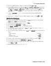
XTAL
Bandpass
Adjustments
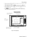
13. On the spectrum analyzer, press
ISPAN),
1, (MHz), and
ICAL).
14. Move the positive DVM test lead to
A5TP7.
15. On the spectrum analyzer, press
AIIJ
CVRR
IF STATE. Wait for the IF ADJUST STATUS
message to disappear before continuing to the next step.
16. Read the voltage displayed on the DVM. If the voltage is less than $6.06 Vdc, turn
A5T200 XTAL CTR 1 clockwise. If the voltage is greater than i-6.26 Vdc, turn XTAL
CTR 1 counterclockwise.
17. Repeat steps 15 and 16 until the voltage reads
t6.16
Vdc
flO0
mV.
Adjustment Procedures 2-23