


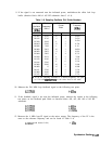
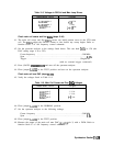
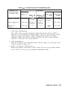
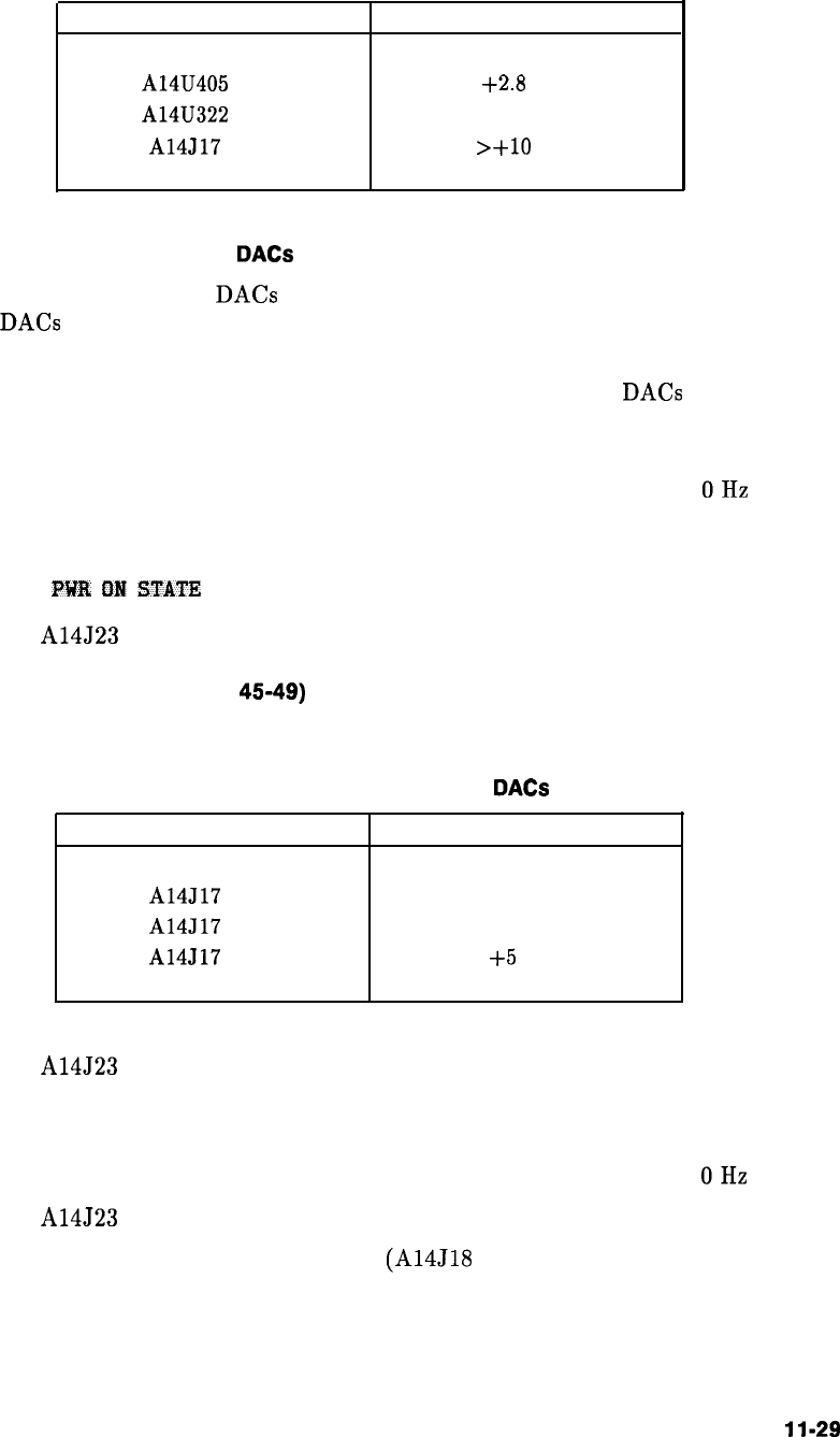
Table 11-8. Voltages in FM Coil and Main Loop Drivers
Measurement Points
Voltages
A14U405 pin 6
+2.8
Vdc
A14U322 pin 2
0 Vdc
A14J17 pin 4
>+10
Vdc
Check main coil coarse and fine
DACs
(steps 41-44)
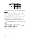
41. The main coil coarse and fine DACs correct any initial pretune errors in the YTO main
coil. The DACs adjust the FM-coil current to zero before any sweep begins. Refer to
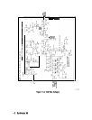
function block J of Al4 frequency control schematic.
42. Set the spectrum analyzer to the settings listed below. This sets both DACs to 128 (the
DAC setting range is 0 to 255).
Centerfrequency
. . . . . . . . . . . . . . . . . . . . . . . . . . . . . . . . . . . . . . . . . . . ...300 MHz
Span
. . . . . . . . . . . . . . . . . . . . . . . . . . . . . . . . . . . . . . . . . . . . . . . . . . . . . . . . . . . . OHz
Trigger . . . . . . . . . . . . . . . . . . . . . . . . . . . . . . . . . . . . . . . . . . . . . . . . . . ..Single.EXT
(with no external trigger connected)
43. Press (SAVE),
PWR
flN
STATE
and turn off the spectrum analyzer.
44. Place jumper A14J23 in the TEST position and turn on the spectrum analyzer.
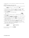
Check main coil tune DAC (steps
4549)
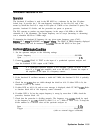
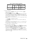
45. Verify the voltages listed in Table 11-9.
Table 11-9. Main Coil Coarse and Fine
DACs
Voltages
Measurement Points
Voltages
A14J17 pin 2 -5 Vdc
A14J17 pin 3
-5 Vdc
A14J17 pin 5
+5
Vdc
46. Place jumper A14J23 in the NORMAL position.
47. Set the spectrum analyzer to the following settings:
Center frequency
. . . . . . . . . . . . . . . . . . . . . . . . . . . . . . . . . . . . . . . . . . . ...300 MHz
Span
. . . . . . . . . . . . . . . . . . . . . . . . . . . . . . . . . . . . . . . . . . . . . . . . . . . . . . . . . . . . OHz
48. Place jumper A14J23 in the TEST position.
49. Measure the output of the main coil tune DAC
(A14J18
pin 3) with a DVM. Refer to
function block E of Al4 frequency control schematic.
Synthesizer Section
11-29