


Using the TAM
The HP 85629B TAM, in conjunction with the HP
8562E/TAM
Interface Software
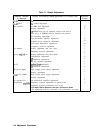
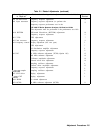
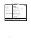
(TAM I/F SW), can be used to perform approximately half of the spectrum analyzer
adjustment procedures. Table 2-4 lists the TAM adjustments and their corresponding manual
adjustments. Refer to Chapter 7, “General Troubleshooting,” for information on loading and
running the TAM I/F SW.
The TAM adjustments do not include procedures for choosing factory-selected components. If
an adjustment cannot be made and a factory-selected component must be changed, refer to
the corresponding manual adjustment.
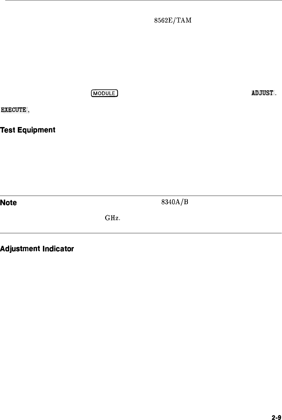
To select an adjustment, press
(m)
to display the TAM main menu, then press
AMUST.
Position the pointer next to the desired adjustment using either the knob or step keys. Press
EXECUTE,
then follow the instructions displayed on-screen.
Test
Equipment
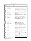
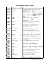
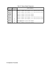
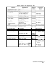
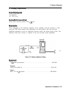
During the TAM adjustments, instructions for setting test equipment controls are displayed.
Table 2-5 lists the test equipment needed to perform each TAM adjustment. Required models
must be used. Substitutions may be made for recommended models. Substitute sources
must operate over the frequency ranges indicated. Recommended substitutes are listed in
the configuration menu. If you must substitute the source with a user-defined model, the
adjustments run faster using a synthesized source rather than an unsynthesized source.
Note
When connecting signals from the HP
8340A/B
(or any microwave source)
to the adjustment, setup, use a high-frequency test cable with minimum
attenuation to 26.5 GHz. HP part number 8120-4921 is recommended for its
ruggedness, repeatability, and low insertion loss.
Adjustment
Indicator
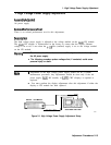
To aid in making adjustments, the TAM displays an
“Analog Voltmeter Display Box” along
the left-hand side of the display. A horizontal line moves inside the box to represent the
needle of an analog voltmeter. A digital readout appears below the box. Tick marks are often
displayed on the inside edges of the box indicating the desired needle position. (The tick
marks and needle are intensified when the needle is within this acceptable region.) During
some adjustments, an arrow appears along the right edge of the box. This arrow always
indicates the highest position the needle has reached. The arrow is useful when a component
must be adjusted for a peak response; if the peak is overshot, the arrow indicates where the
peak was. The component can be readjusted until the needle is at the same position as the
arrow.
Adjustment Procedures
2-9