


Note
Ideally, the DVM should read the voltage written on the label of the
A6Al
HV module. If necessary, perform the “High Voltage Power Supply”
adjustment in Chapter 2, “Adjustment Procedures.”
5. If the DVM does not read approximately
+llO
Vdc, measure the voltage on
A6U401 pin 10. This is the LHVSHUT-DOWN signal and should be near
+5
Vdc.
6. If LHVSHUT-DOWN is low, suspect a bad connection along W8 between the A6 power
supply and the Al7 CRT driver.
7. If LHVSHUT-DOWN is correct, connect an oscilloscope to
A6TP402.
Connect the scope
probe negative lead to TP401. Set the oscilloscope to the following settings:
Sweep time
. . . . . . . . . . . . . . . . . . . . . . . . . . . . . . . . . . . . . . . . . . . . . . . . . . . . . . . . .
10
psjdiv
Vertical scale
. . . . . . . . . . . . . . . . . . . . . . . . . . . . . . . . . . . . . . . . . . . . . . . . . . . . . . ..lO
V/div
8. A nearly-sinusoidal waveform, greater than 30 Vp-p, with an approximately i-18 Vdc
offset, should be observed.
9. If the waveform is a dc voltage near 0 Vdc with narrow, positive- and negative-going
pulses, the
A6Al
HV module is faulty. If the waveform is a dc voltage near
+18
Vdc with
narrow, positive- and negative-going pulses, connect the probe to TP403.
10. If the waveform at TP403 is a sawtooth waveform with a 1.8 V amplitude, the
A6Al
HV
module is faulty.
11. If the TP403 waveform has pulses similar to those on TP402, the A6 power supply is
probably faulty.
CRT
Supply
Dropping
Out
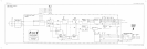
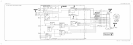
See function block K of A6 power supply schematic diagram in the component-level
information binder.
The CRT supply is a separate switching supply which provides the
+llO
Vdc for the
Al7 CRT driver from a winding on the
A6Al
HV module. The CRT supply operates at
approximately 30 kHz. The exact frequency is determined by the inductance of the primary
winding of
A6AlTl
and A6C407. The supply will only operate if the LHVSHUT-DOWN
line is high.
If the power supply keeps dropping out, there is probably a short on the Al7 CRT driver
assembly.
1. Disconnect W8 from A6J4.
2. Connect an IC clip to
U401
and connect a jumper between
U401
pin 10 and TP308
(i-5 Vdc).
3. Connect a voltmeter to TP405 and set the luNE) switch on.
4. Check TP405 for a voltage of approximately
fll0
Vdc. It will probably measure higher
since there is no load on the supply.
5. If the voltage at TP405 is correct, suspect a short on A17. If the voltage at TP405 is not
correct, check pin
U401
pin 8 for a sawtooth signal. The sawtooth should be flat-topped
and about 5 Vp-p at a frequency of about 30 kHz.
6. If the sawtooth is not flat-topped, suspect U402A and its associated circuitry.
13-16 Display/Power Supply Section