


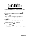

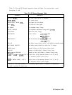
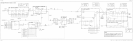
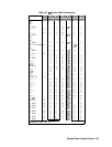
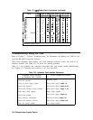
Table 12-5 lists the RF Section mnemonics shown in Figure 12-8, and provides a brief
description of each.
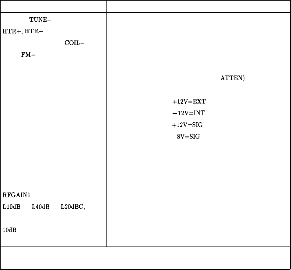
Table 12-5. RF Section Mnemonic Table
Mnemonic
Description
TUNE+,
TUNE-
YTF Tune Signal (SYTF or RYTHM)
HTR+,
HTR-
YTF Heater Power
MAIN COIL+, MAIN
COIL-
YTO Main Coil Tune Signal
FM+,
FM-
YTO FM Coil Tune Signal
LO SENSE
LO Amplitude Sense Voltage
LEVEL ADJUST
LO Amplitude Adjustment Voltage (PIN
ATTEN)
GATE BIAS
LODA Gate Bias Voltage
HEXTMIXB
External Mixer:
+12V=EXT
MIX
-
lZV=INT
MIX
HSIGIDOFFA
SIG ID Oscillator ON:
+lSV=SIG
ID OFF
-8V=SIG
ID ON
PIN SW
PIN Diode Switch Control (SYTF or RYTHM LO Band/HI Band)
PIN DIODE SWITCH
PIN Diode Switch Control For 2ND Conv. IF Output
MIXER BIAS
Detected Voltage on 2ND Converter Mixer Diode
RFGAIN
Voltage to Control Gain of Flatness Comp. Amps.
RFGAINl
and RFGAIN2
Currents to Drive PIN Diodes in Flatness Comp. Amps.
LlOdB A, L40dB B, LSOdBC, LDC D Control Lines to Set Attenuator Sections A, B, C, and D
to Attenuate Position (Active Low)*
1OdB
A, 40dB B, 20dB C, LAC D
Control Lines to Set Attenuator Sections A, B, C, and D
to Attenuate Position (Active High)*
* Section D of the input attenuator is a dc blocking capacitor which is switched in or bypassed by
the LDC D and LAC D control lines.
RF Section 12-23