


Procedure 2. Al Front Frame/Al8 CRT
Procedure 2.
Al Front Frame/Al8 CRT
Removal
Warning
The voltage potential at
A8AlW3
is
+9
kV.
Disconnect at the CRT with
caution1
Failure to properly discharge
A8AlW3
may result in severe
electrical shock
to
personnel and damage to the instrument.
1. Remove the spectrum analyzer cover assembly as described in “Procedure 1. Spectrum
Analyzer Cover.”
2. Fold out the A2, A3, A4, and A5 assemblies as described in “Procedure 5. A2, A3, A4,
and A5 Assemblies Removal,” steps 2 through 6.
3. Disconnect
AlAlWl
from A3J602.
4. Place the spectrum analyzer top-side-up on the work bench.
5. Connect the spectrum analyzer line-power cord to provide proper grounding while
discharging the
A6AlW3
post-accelerator cable. Make sure that the spectrum analyzer
line-power switch is in the off position.
6. Connect a high voltage probe
(lOOO:l),
such as the HP 34111A to a voltmeter with a
10
megohm
input.
7. Connect the clip lead of the probe (ground) to the chassis of the spectrum analyzer.
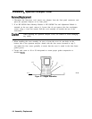
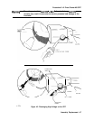
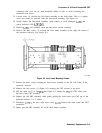
8. Slip the tip of the high voltage probe under the rubber shroud of the
A6AlW3
post-accelerator cable to obtain a reading on the voltmeter. See Figure 4-2.
9. Keep the high voltage probe on the post-accelerator connector until the voltage has
dropped to a voltmeter reading of less than 5
mV
(less than 5 V at the connector). This
normally takes about 30 seconds.
10. Disconnect the line-power cord from the spectrum analyzer.
Warning
To avoid possible electrical shock, in the next step, use a screwdriver having a
conductive metal shank and tip, with an insulated handle.
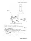
11. Connect one end of a wire clip lead to a small screwdriver having a conductive shank
and tip. Connect the other end of the clip lead to the CRT shield assembly as shown
in Figure 4-2. Hold the insulated screwdriver handle and slip the tip of the screwdriver
under the rubber shroud of the
A6AlW3
post-accelerator cable, shorting the cable to
ground through the CRT shield assembly. See Figure 4-2.
12. Using a small screwdriver with the shank in contact with the CRT shield assembly, slip
the tip of the screwdriver under the
A6AlW3
post-accelerator cable rubber shroud and
short the cable to ground on the CRT shield assembly.
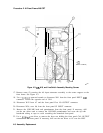
13. Pry out the black grommet protecting post-accelerator cable
A6AlW3
from the CRT
shield assembly.
14. Carefully unsnap the
A6AlW3
post-accelerator cable from the CRT and discharge it by
shorting the cable to chassis ground on the CRT shield assembly.
Assembly Replacement 4-5