


6. Sampling Oscillator Adjustment
2. Press (PRESET) on the spectrum analyzer and set the controls as follows:
Center frequency . . . . . . . . . . . . . . . . . . . . . . . . . . . . . . . . . . . . . . . . . . .
..2126MHz
Span. . . . . . . . . . . . . . . . . . . . . . . . . . . . . . . . . . . . . . . . . . . . . . . . . . . . . . . . . . . . OHz
3. Set the HP 3456A controls as follows:
Function . . . . . . . . . . . . . . . . . . . . . . . . . . . . . . . . . . . . . . . . . . . . . . . . . . . DC VOLTS
Range . . . . . . . . . . . . . . . . . . . . . . . . . . . . . . . . . . . . . . . . . . . . . . . ..lOV.MANUAL
Sampling
Oscillator
Adjustment
4. Connect the negative DVM test lead to A15J200 pin 6. Connect the positive DVM lead to
A15J200 pin 13.
5. Adjust A15C210 VCO RANGE for a DVM reading of 5.05 V f0.05 V.
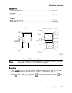
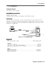
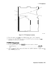
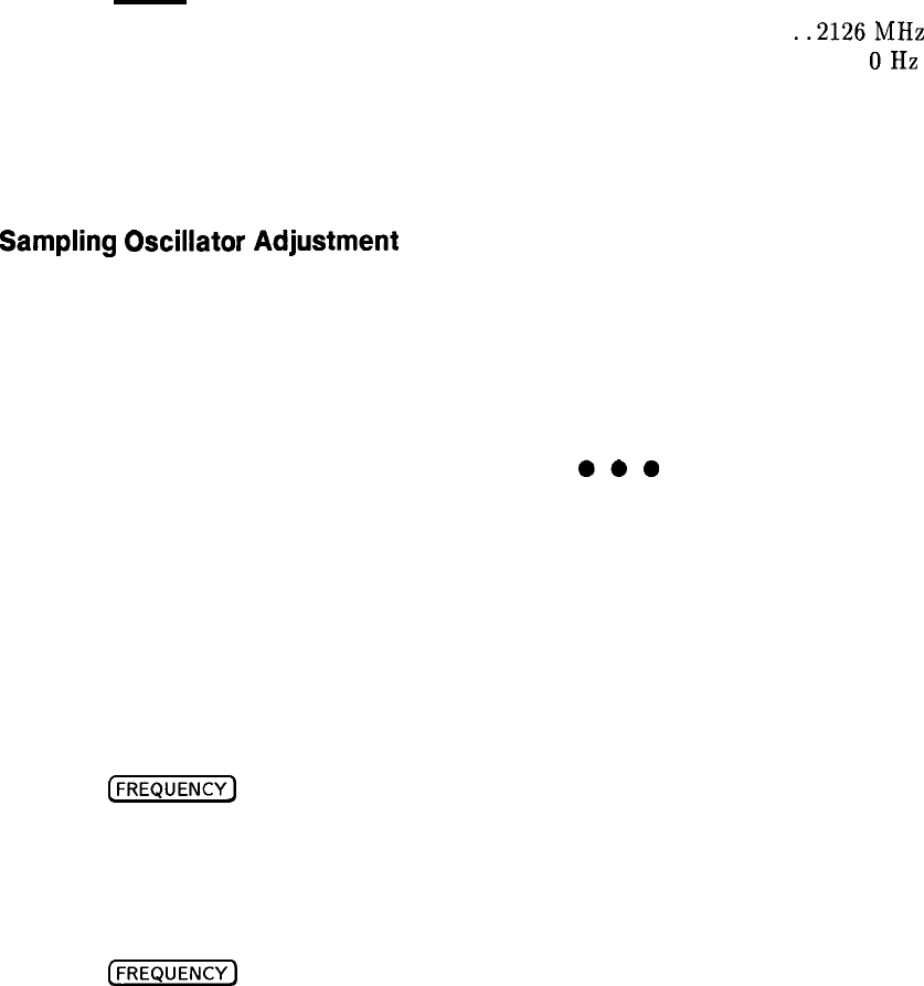
PIN 2 . . . l l . l
. PIN 16
PIN 1 n . . .
l
SP114E
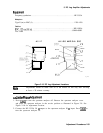
Figure 2-12. TAM Connector Pin Locations
Sampler
Match
Adjustment
6. Connect the negative DVM test lead to A15J400 pin 6, and the positive DVM test lead to
A15J400 pin 1.
7. Press
(-1
and set the spectrum analyzer center frequency to 2302.3 MHz. This
sets the sampling oscillator to 291.667 MHz.
8. Adjust
A15ClOO
SMPL MATCH to peak the voltage displayed on the DVM.
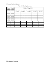
9. Record the displayed voltage in Table 2-11 as the displayed voltage for the sampling
oscillator frequency of 291.667 MHz.
10. Press
(-1
on the spectrum analyzer.
Use the keypad to set the spectrum analyzer
center frequency to the frequencies listed in Table 2-11. At each listed frequency, record
the displayed voltage in the table.
11. If the difference between the maximum and minimum voltages is less than 0.50 V, and all
voltage readings are between
+.5
and
+2.5
Vdc, proceed to step 15.
12. Locate the center frequency at which the voltage is lowest. Use the keypad to set the
spectrum analyzer to this frequency.
13. Readjust SMPL MATCH to set the displayed voltage to 0.8 fO.l Vdc.
14. Set the spectrum analyzer center frequency to 2302.3 MHz and repeat steps 9 through 13.
15. Move the positive DVM test lead to A15J400 pin 3. Check that the measured voltage is
the negative of the voltage at pin 1, within fO.l Vdc.
16. Disconnect the DVM probes from A15J400.
Adjustment Procedures 2-35