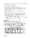
6.
Set the HP
8566A/B
as follows:
7.
8.
Center frequency . . . . . . . . . . . . . . . . . . . . . . . . . . . . . . . . . . . . . . . . . . . . . . 10.7 MHz
Span . . . . . . . . . . . . . . . . . . . . . . . . . . . . . . . . . . . . . . . . . . . . . . . . . . . . . . . . . . . . 2kHz
Reference level . . . . . . . . . . . . . . . . . . . . . . . . . . . . . . . . . . . . . . . . . . . . . . . .
+lO
dBm
Sweep . . . . . . . . . . . . . . . . . . . . . . . . . . . . . . . . . . . . . . . . . . . . . . . . . . . . . . . . . . . Single
Press TRACE A [CLEAR-WRITE) on the HP
8566A/B.
Trigger a sweep on the signal generator and on the HP
8566A/B
simultaneously. The
HP
8566A/B
should display a 3 dB bandwidth of approximately 500 Hz.
9.
Reconnect W27 (coax 3) to
A5J5
and W29 (coax 7) to A5J3.
4.8
kHz
and
10.7
MHz
IF
Filters
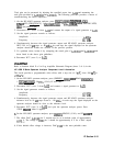
1. On the HP 85623 spectrum analyzer, press
[PRESET),
(-1,
300
(K],
[El,
600 [Hz),
a,
and IF
$DJ
OFF.
2. Disconnect W29 (coax 7) from
A5J3.
Set the signal generator for a 10.7 MHz signal at
-60
dBm
and connect it to
A5J3.
3. Fine tune the frequency of the signal generator to center the signal on the HP 85623
spectrum analyzer display. Set the signal generator to sweep one 2 kHz span about this
center frequency.
4. On the HP 85623 spectrum analyzer, press
[WSVVP).
5. Set the HP
8566A/B
to 4.8 kHz center frequency and 2 kHz span.
Caution
Damage to the HP
8566A/B
results if a dc block is not used. The
HP
8566A/B
and many other spectrum analyzers have dc-coupled inputs and
cannot tolerate dc voltages on their inputs.
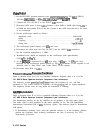
6. Connect the VIDEO OUTPUT (
rear panel) of the HP 85623 spectrum analyzer through a
20 dB attenuator and dc block to the input of the HP
8566A/B.
Set the sweep time of the
HP
8566A/B
to 10 seconds.
7. Set the HP
8566A/B
to single trigger and press TRACE A (CLEAR-WRITE]. Trigger a sweep
on the HP
8566A/B
and on the signal generator simultaneously. The HP
8566A/B
should
show a 3 dB bandwidth of 600 Hz
flO0
Hz.
8. Reconnect W29 (coax 7) to
A5J3.
10.8952
MHz
VCXO
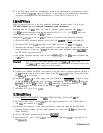
Refer to function block E of A4 Log Amplifier Schematic Diagram (sheet 2 of 4) in the
HP 8560 E-Series Spectrum Analyzer Component Level Information.
The purpose of the 10.6952 MHz voltage-controlled crystal oscillator (VCXO) is to provide an
LO for down-converting the peak of the 10.7 MHz IF filter
passband
to 4.8 kHz. Since the
peak of the
passband
of the 10.7 MHz IF filters is 10.7 MHz f300 Hz, the frequency of the
VCXO is between 10.6949 MHz and 10.6955 MHz. This frequency can best be measured at
the collector of A4Q202.
9-16
IF Section


