


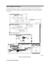
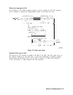
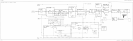
Third Converter (part of A15)
The third converter down-converts the 310.7 MHz IF to 10.7 MHz. A PIN-diode switch selects
the LO signal used. For normal operation, a 300 MHz LO signal is used. The signal is derived
from the 600 MHz reference PLL. During signal identification (SIG ID ON), the 298 MHz SIG
ID oscillator is fed to the double balanced mixer on alternate sweeps. Signal identification is
available as Option 008.
Flatness Compensation Amplifiers (part of
AM)
The flatness compensation amplifiers amplify the output of the double-balanced mixer. The
amplifier variable gain (0 to 45
dB)
compensates for flatness variations within a band. Band
conversion loss is compensated by step gain amplifiers in the IF section.
Control for the amplifiers originates from two DACs on the A3 Interface assembly. (DAC
values are interpolated approximately every 17 MHz based on data obtained during the
frequency response adjustment.) The Al5 flatness-compensation control circuitry converts the
RF GAIN voltage, from A3, into two currents: RF GAIN1 and RF GAIN2. These currents
drive PIN diodes in the flatness compensation amplifiers.
General Troubleshooting 7-45