


12
RF Section
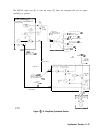
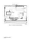
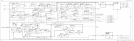
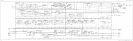
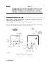
The RF Section converts the input signal to a 10.7 MHz IF (Intermediate Frequency). See the
detailed block diagram, Figure 12-8.
Note
The block diagrams for the Al4 and Al5 assemblies are located in Chapter 11,
“Synthesizer Section.”
Troubleshooting Using the TAM
Low Band Problems
High Band Problems
Low and High Band Problems
A7 LO Distribution Amplifier
A8 Low Band Mixer
A9 Input Attenuator
Al3 Second Converter
Al4 Frequency Control Assembly
LODA Drive
Control Latch for Band-Switch Driver
YTF Driver Circuit
Al5 RF Assembly
Confirming a Faulty Third Converter
Confirming Third Converter Output
Third Converter
Flatness Compensation Control
Control Latches
SIG ID Oscillator (Option 008)
10 MHz Reference
Caution
All of the RF assemblies are extremely sensitive to Electrostatic Discharge
(ESD). For
ur
f ther information regarding electrostatic cautions, refer to
“Electrostatic Discharge” in Chapter 1, “General Information.”
RF Section 12-1