


3. IF
Bandpass
Adjustment
Procedure
1. Turn the spectrum analyzer off by pressing
@.
Disconnect the power cord. Remove the
spectrum analyzer cover and fold down the A2 controller, A3 interface, A4 log amp, and
A5 IF assemblies. Reconnect the power cord. Turn the spectrum analyzer on and allow it
to warm up for at least 30 minutes.
2. Connect the negative DVM lead to pin 6 of
A5J6.
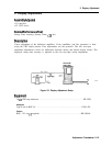
See Figure 2-5 and Figure 2-6. Set the
HP 3456A controls as follows:
Function . . . . . . . . . . . . . . . . . . . . . . . . . . . . . . . . . . . . . . . . . . . . . . . . . . . DCVOLTS
Range . . . . . . . . . . . . . . . . . . . . . . . . . . . . . . . . . . . . . . . . . . . . . . . . . . . . . . . . . . . 1OV
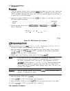
3. On the spectrum analyzer press,
(-1,
l=),
2,
LMHz),
ICAL),
and IF
AD3
IX OFF so
OFF is underlined.
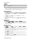
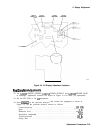
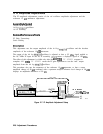
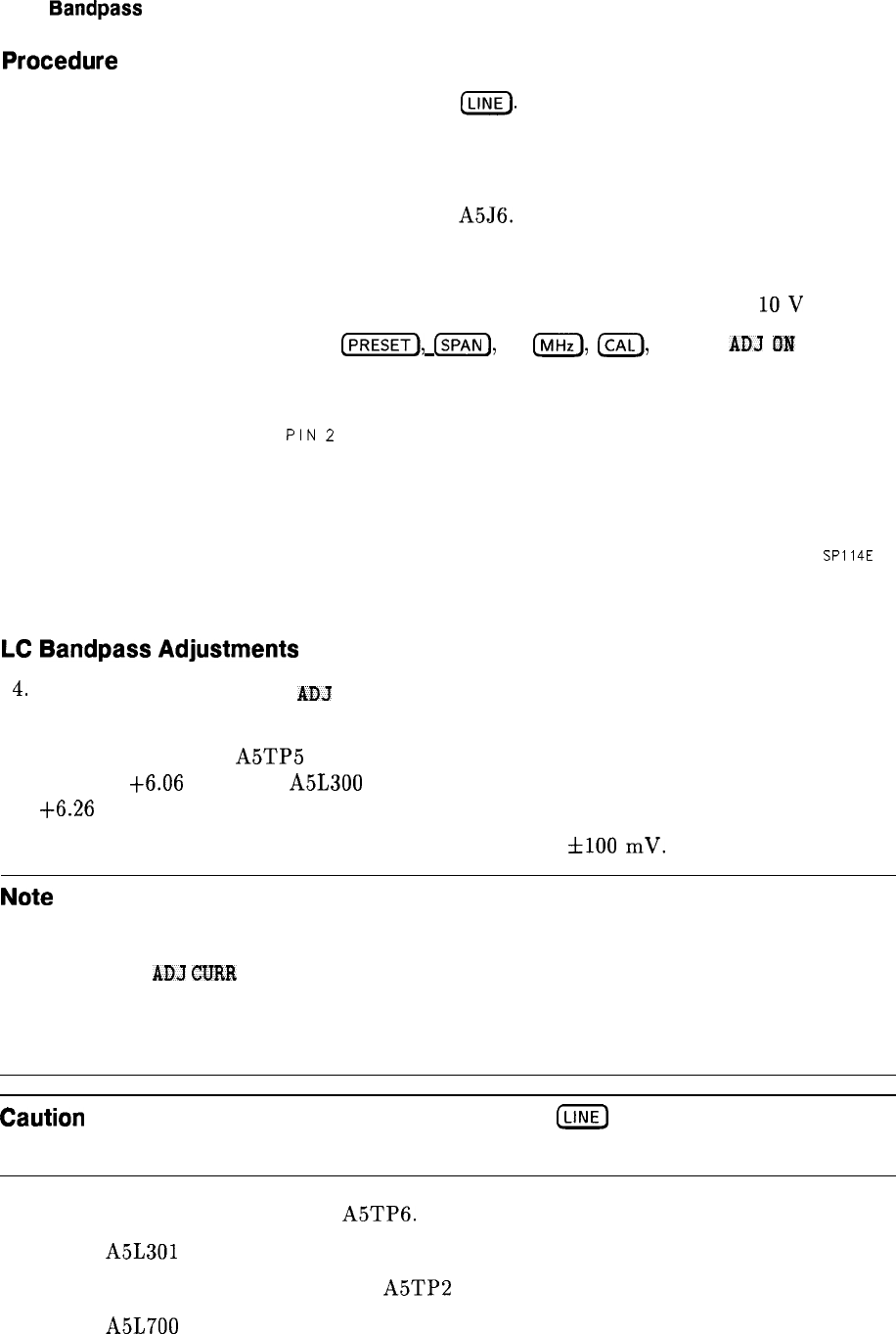
PIN
2
. . l . . . . . PIN 16
PIN 1 n . . .
l .m
SP114E
Figure 2-8. TAM Connector Pin Locations
LC
Bandpass
Adjustments
4.
On the spectrum analyzer, press
AD3
CURR IF STATE.
Wait for the
IF ADJUST STATUS
message to disappear before continuing with the next step.
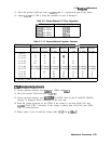
5. Read the voltage on
A5TP5
(th
is
is an empty-hole type of test point). If the voltage is
less than
t6.06
Vdc, turn A5L300 LC CTR 1 clockwise. If the voltage is greater than
+6.26
Vdc, turn LC CTR 1 counterclockwise.
6. Repeat steps 4 and 5 until the voltage reads i-6.16 Vdc
flO0
mV.
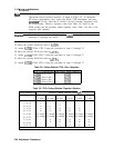
Note
If the range for the LC CTR adjustment is insufficient, replace the
appropriate factory-selected capacitor as listed in Table 2-6. To determine
the correct replacement value, center the LC CTR adjustment and press
AD3
CURR
IF STATE. After the IF ADJUST STATUS message disappears, read
the DVM display. Choose a capacitor value from Table 2-7, based on the
DVM reading and the presently loaded capacitor value. Table 2-10 lists a few
capacitor part numbers.
Caution
Turn the spectrum analyzer off by pressing luNE) to the off position before
removing or replacing any shield.
7. Move the positive DVM lead to
A5TP6.
8. Adjust
A5L301
LC CTR 2 by repeating steps 4 through 6.
9. Move the positive DVM test lead to
A5TP2
(th
is is a resistor-lead type of test point).
10. Adjust A5L700 LC CTR 3 by repeating steps 4 through 6.
2-22 Adjustment Procedures