


Test
Connectors
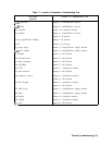
The TAM uses a built-in dc voltmeter and DAC to measure voltages on any one of the “test
connectors” (or test jacks) located throughout the spectrum analyzer.
Revision Connectors
One test connector on each assembly is reserved as a “revision connector.” The TAM uses the
revision connector to identify the assembly design revision. A “revision voltage” placed onto
one measured signal line (MSL) pin, indicates design changes.
The TAM must be plugged into the revision connector first to determine which tests to use for
the assembly. If the revision connector has not been probed, a message will appear instructing
you to connect the probe to the revision connector and press TEST. You can then probe the
rest of the assembly connectors.
Note
If the revision of the PC board is newer than the TAM, a message will be
displayed stating that the revision code for this board is not known by this
module. The choices presented are to use the test for the latest known
revision board, measure only voltages, or exit. In general, most points will not
change from one board revision to another, so using the most current tests
is still very useful. However, any failure should be verified using the manual
troubleshooting procedures before doing a repair.
Inconsistent
Results
Many of the signals measured by the TAM are digitally controlled. If inconsistent results are
obtained, or if failures appear in unrelated areas, the digital control may be at fault. Refer to
the manual troubleshooting procedures for those assemblies to isolate those failures.
Erroneous
Results
If the TAM manual probe troubleshooting seems to be giving erroneous results, its
performance can be checked by placing the probe on the TAM test connector
(A2Jll)
located
on the A2 controller assembly and executing the manual probe diagnostics. If either of the
tests fail, the TAM is malfunctioning and should be serviced.
Blank
Display
It is possible to use the TAM manual probe troubleshooting without a display if an HP-IB
printer is available. Refer to Chapter 13, “Display/Power Supply Section,” for more
information.
_-
General Troubleshooting 7-13