


3. IF
Bandpass
Adjustment
3. IF
Bandpass
Adjustment
Assembly
Adjusted
A5 IF assembly
Related
Performance
Test
Resolution bandwidth accuracy and selectivity
Description
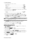
The center frequency of each IF
bandpass
filter pole is adjusted by DAC-controlled varactor
diodes and an inductor (for the LC poles) or a transformer (for the crystal poles). The
inductors and transformers are for coarse tuning and the varactors are for fine tuning by the
microprocessor. The inductors and transformers are adjusted such that the varactor diodes
are biased near the middle of their capacitance range. The varactor diode bias is measured
with the DVM.
Note
This procedure is not a routine adjustment. It should be performed only
if repairs to the A5 IF assembly are made. If the entire A5 IF assembly is
replaced, the assembly arrives pre-adjusted from the factory and requires no
further adjustment.
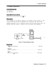
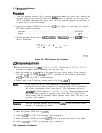
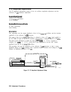
SPECTRUM
ANALYZER
5
if
BOARD
A3
-
A2
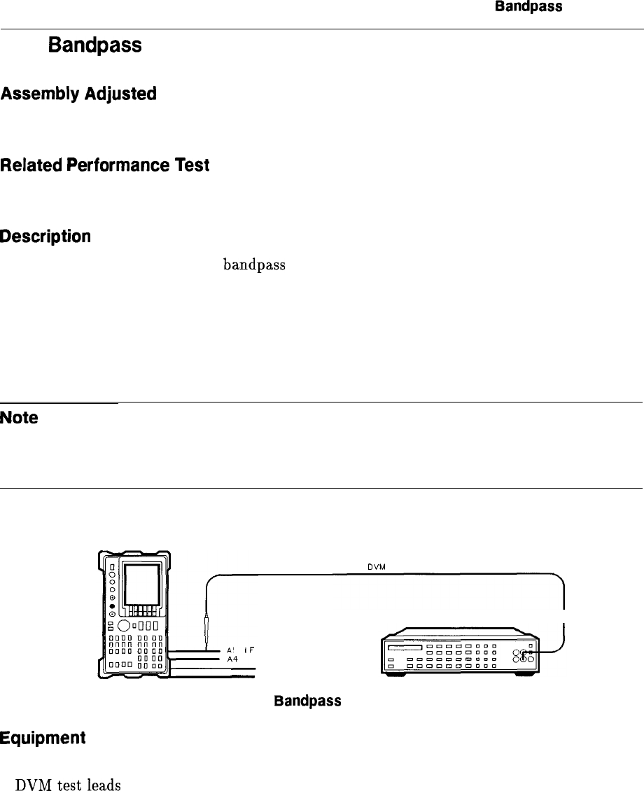
DVM
TEST LEADS
DIGITAL VOLTMETER
I
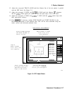
Figure 2-5. IF Bandpass Adjustment Setup
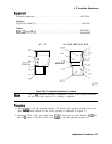
Equipment
Digital voltmeter
................................................
HP 3456A
DVMtestleads
................................................
HP 34118A
Special tuning tool (for slot-type tuning slugs)
.......................
8710-1010
Special tuning tool (for fork-type tuning slugs)
.......................
8710-0772
SK15
Adjustment Procedures 2-21