


Note
The following measurements should be made with a high-voltage probe, such
as the HP 34111A. When using the high-voltage probe, connect the ground
lead securely to the spectrum analyzer chassis.
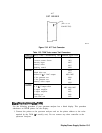
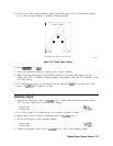
7. Carefully measure the grid voltage at A17J7 pin 6, and the cathode voltage at
A17J7
pin
4. The display will work with a cathode voltage of -2450 V
f250
V, provided the grid
voltage
(A17J7
pin 6) is 30 to 100 V more negative than the cathode.
A17Rl1,
CUTOFF,
should be able to adjust the voltage difference over a 60 V range to account for tube
variations, and achieve proper intensity.
8. If the grid and cathode voltages are correct, turn off the spectrum analyzer and check
CR10 with an ohmmeter. If CR10 is good, suspect the
A18Vl
CRT.
9. If the grid and cathode voltages are too low, turn off the power and disconnect W8 from
the base of
A18Vl
CRT, and recheck the grid and cathode voltages.
10. If the grid and cathode voltages are still too low, refer to “CRT Supply” in this chapter
and the “High-Voltage Power Supply Adjustment” procedure in Chapter 2, “Adjustment
Procedures.”
11. If voltages are correct when the tube is disconnected, the CRT is probably defective.
Caution
The pins on the
A18Vl
CRT bend easily. Be careful not to bend pins when
connecting W8 to
A18Vl.
Display/Power Supply Section
13-l 1