


5.
3.
4.
5.
6.
A4
1.
2.
3.
4.
5.
6.
7.
8.
9.
10.
X
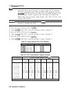
Log Amplifier Adjustments
Set the spectrum analyzer controls as follows:
Center frequency
. . . . . . . . . . . . . . . . . . . . . . . . . . . . . . . . . . . . . . . . . . . . . ...15 MHz
Span . . . . . . . . . . . . . . . . . . . . . . . . . . . . . . . . . . . . . . . . . . . . . . . . . . . . . . . . . . . . . . . ..O
Reference level . . . . . . . . . , . . . . . . . . . . . . . . . . . . . . . . . . . . . . . . . . . . . . . . -10
dBm
dB/division . . . . . . . . . . . . . . . . . . . . . . . . . . . . . . . . . . . . . . . . . . . . . . . . . . . 1 dB/DIV
Resolution bandwidth . . . . . . . . . , . . . . . . . . . . . . . . . . . . . . . . . . . . . . . . . . . 300 kHz
IFADJ . . . . . . . . . . . . . . . . . . . . . . . . . . . . . . . . . . . . . . . . . . . . . . . . . . . . . . . . . . . OFF
Set up an HP 3335A as follows:
Frequency . . . . . . . . . . . . . . . . . . . . . . . . . . . . . . . . . . . . . . . . . . . . . . . . . . . ...15 MHz
Amplitude . . . . . . . . . . . . . . . . . . . . . . . . . . . . . . . . . . . . . . . . . . . . . . . . . . . . -18dBm
Press (CAL),
ADJ
CURR
IF STATE, wait for the analyzer to complete adjustments, then
?ress
[MKR).
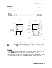
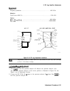
Adjust A4R445 for maximum on-screen amplitude. Refer to Figure 2-10 for the location of
44R445.
Linear
Fidelity
Adjustment
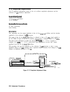
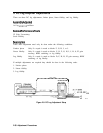
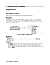
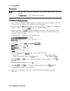
Press (LINE) to turn the spectrum analyzer off. Remove the spectrum analyzer cover
and place the spectrum analyzer in the service position as illustrated in Figure 2-9. See
Figure 2-10 for adjustment location.
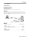
Connect the HP 3335A 50
R
output to the spectrum analyzer 50
fi
input. Press
IuNE)
to
turn the spectrum analyzer on.
Press
(-1,
(m),
LINEAR, MORE
I.
of 3 , AMPTD UNITS
,dBm
,
a,
IF
AD.7
ON OFF, (OFF).
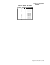
Set the spectrum analyzer controls as follows:
Center frequency
. . . . . . . . . . . . . . . . . . . . . . . . . . . . . . . . . . . . . . . . . . . . ...15 MHz
Span . . . . . . . . . . . . . . . . . . . . . . . . . . . . . . . . . . . . . . . . . . . . . . . . . . . . . . . . .
..5MHz
Resolution bandwidth
. . . . . . . . . . . . . . . . . . . . . . . . . . . . . . . . . . . . . . . . . . 300 kHz
Reference level
. . . . . . . . . . . . . . . . . . . . . . . . . . . . . . . . . . . . . . . . . . . . . . . -10
dBm
Set up an HP 3335A as follows:
Frequency . . . . . . . . . . . . . . . . . . . . . . . . . . . . . . . . . . . . . . . . . . . . . . . . . . ...15 MHz
Amplitude . . . . . . . . . . . . . . . . . . . . . . . . . . . . . . . . . . . . . . . . . . . . . . . . . . . -10
dBm
Press [PEAK SEARCH),
MAftKER
DELTA .
Reduce the HP 3335A input power to -58 dBm.
If the delta marker amplitude reads -40
dB
f2
dB, no adjustment is necessary.
If the signal is lower on the screen than expected (delta marker amplitude reads less than
-42dB),
then adjust A4R544 (see Figure 2-10) f
or an even lower level and press (CAL],
ADJ
CURR
IF STATE . Allow sufficient time for the analyzer to complete the adjustment.
If the signal is higher on the screen than expected (delta marker amplitude reads greater
than -38
dB),
then adjust A4R544 for an even higher level signal and press
ICAL),
ADJ
CURR
IF STATE. Allow sufficient time for the analyzer to complete the adjustment.
2-32 Adjustment Procedures