


Replacement
Procedure 10.
Al6 Fast ADC and Al7 CRT Driver
1. Connect W7, W8,
W9,
A6AlW2,
and
AlSWl
to the Al7 CRT driver assembly. Place the
assembly into the center-deck mounting slot next to the CRT assembly.
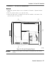
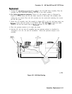
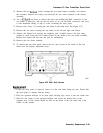
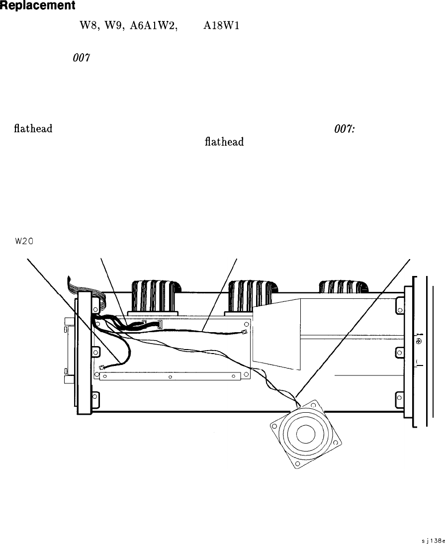
2. For Option
007
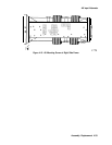
spectrum analyzers: Connect all Al6 assembly cables as illustrated in
Figure 4-21 which shows the left side frame removed so that proper Al6 assembly cable
routing may be viewed. Place the Al6 assembly into the center-deck mounting slot nearest
the left side frame.
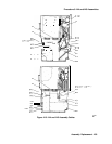
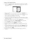
3. Secure the Al7 assembly (and Al6 assembly in Option 007) to the left side frame using two
flathead
screws (and two spacers in non-Option 007). For Option
007:
Attach the board
mounts to the left side frame using two
flathead
screws (1). See Figure 4-20.
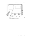
4. Place the spectrum analyzer on its right side frame.
5. Fold the A2, A3, A4, and A5 assemblies into the spectrum analyzer as described in
“Procedure 5. A2, A3, A4, and A5 Assemblies.”
Secure the spectrum analyzer cover
assembly.
w20
w59
COAX 6
w7
COAX 839
w5
-
B
4
-
sj138e
Figure 4-21. Al6 Cable Routing
Assembly Replacement 4-41