


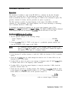
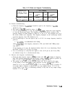
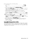
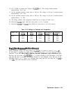
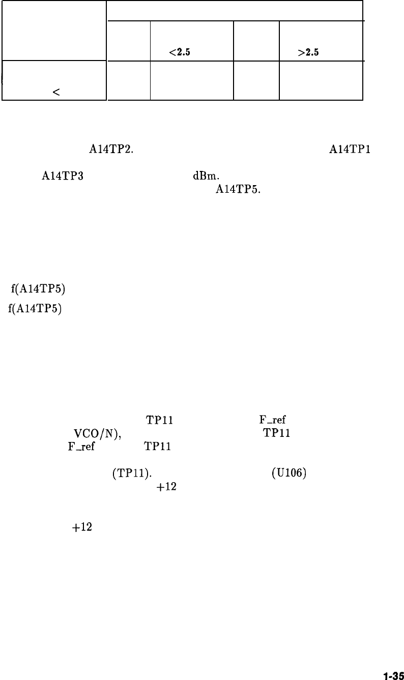
Table 11-12. Divider and Integrator Troubleshooting
Measured VCO
Frequency Relative
to Expected Value
Measured > expected
Measured < expected
TP6 Frequency
zero
<2.5
MHz
2.5 MHz
>2.5 MHz
Dividers
Dividers
Dividers Det or integrator
Both
Det or integrator Dividers
Dividers
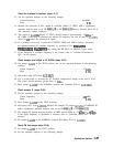
10. Divider troubleshooting:
a. Check the frequency at
A14TP2.
It should be equal to the frequency at
A14TPl
divided by two.
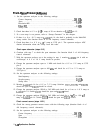
b. The signal at
A14TP3
should be above -14
dBm.
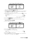
c. Use an analog oscilloscope to view the signal at
A14TP5.
Adjust the scope triggering
to view the divide-by-16 signal. The frequency at this point will be varying as the
prescaler changes its divide number to either 16, 17, 20, or 21. The prescaler uses 16 as
the divide number most frequently. The frequency displayed on the oscilloscope should
equal the frequency from TP2 divided by 16.
d. Use an oscilloscope to view the signal at pin 8 of U112. Its average frequency should be
given by:
f =
f(A14TP5)
x 80 MHz/RAW OSC FREQ
where:
f(A14TP5)
is the frequency measured at TP5, and RAW OSC FREQ comes
from step 4.
If the frequency is in error, the fractional divider, block AS, is not functioning. Check
that FRAC N RUN on U113 pin 39 is high.
e. Use an oscilloscope to verify that the signals at N-in (U112 pin 8) and N-out (TP6)
are identical except for a sub-microsecond delay.
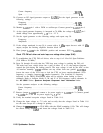
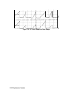
11. Detector and integrator troubleshooting:
a. Check the phase detector output on
TPll
in block AO. If
F-ref
is higher in frequency
than TP6 (reclocked
VCO/N),
then the average voltage at
TPll
should be positive by
0.05 V to 10 V. If
F-ref
is lower,
TPll
should be -0.05 V to -10 V.
b. The polarity of the output of the loop gain (block AP, TP12) should be the same
as the polarity of the input
(TPll).
The integrator op amp (U106) output (TP13)
should try to go very positive (about
+12
V) if its average input (TP12) is positive. If
its average input is negative, it should try to go very negative (about -12 V). If its
average input is zero and it is functioning correctly, it may take on any output voltage
between -12 V and
+12
V.
Synthesizer Section
1
l-35