


7. If the sawtooth is correct, check the base of Q401 for 30 kHz pulses.
8. If the duty cycle is high, but there is no i-110 Vdc, suspect the bridge rectifier, CR401
through CR404.
Buck
Regulator
Control
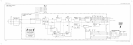
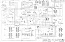
See function block H of A6 power supply schematic diagram in the component-level
information binder.
The buck regulator control pulse-width modulates the buck regulator and provides a
synchronized signal to the DC-DC converter control circuitry. The buck regulator control
has two feedback paths. The first is the output of the buck regulator, which provides coarse
regulation. The second is the feedback circuit which samples and compares the j-6.8 Vdc
output of the output rectifier.
U202A and associated circuitry sense the output of the input rectifier and will turn off
U203
if the voltage at TP108 goes below approximately
+170
Vdc. Also, it will not allow
U203
to
start up until this voltage exceeds
t215
Vdc. A low on the output of U202A will also clear
the overcurrent latch in the DC-DC converter control circuitry.
Thermal shutdown occurs when RT201, mounted on a large heatsink, reaches a temperature of
100 C. When this occurs, the voltage at
U203
pin 13 exceeds 0.6 V and inhibits pulses to the
buck regulator.
R203, R204, R226, and associated circuitry provide feedforward for
U203.
This makes the
loop gain independent of input line voltage and cancels 120 Hz ripple by more than 10 dB.
U202D and its associated circuitry permit the power supply to start up at low line voltages
at low temperatures. At low line voltages U202D will draw charge away from C206 through
R205. This allows the buck regulator to turn on and draw current through the thermistors in
the input rectifier. This warms up the thermistors, thereby decreasing their resistance and
increasing the voltage at TP108. When the voltage is sufficiently high at TP108, the output of
U202D will open and C206 will be allowed to charge normally.
U202B converts the sawtooth at TP204 to a squarewave to drive the DC-DC converter control
circuitry. The frequency of the sawtooth is determined by the resistance at pin 7 of
U203
and
the capacitance at pin 8 of U203.
DC-DC
Converter
Control
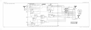
See function block I of A6 power supply schematic diagram in the component-level
information binder.
The DC-DC converter control circuitry divides the 80 kHz squarewave from U202B and
generates two complementary 40 kHz squarewaves to drive the
FETs
in the DC-DC converter.
Also, U202C and its associated circuitry monitor the voltage across resistors R112 through
R117 in the DC-DC converter. When the current through the
FETs
in the DC-DC converter
exceeds 1.8 A, the voltage across the resistors will cause the output of U202C to go high. This
sets a latch in U204 which turns off U203.
Display/Power Supply Section 13-17