


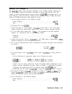

16. Use a DVM to monitor the voltage at A14J18 pin 4. The voltage should measure
approximately -8.45 Vdc.
17. Set the spectrum analyzer sweep time to 100 ms. The voltage at J18 pin 4 should measure
approximately -4.21 Vdc.
18. Set the spectrum analyzer sweep time to 200 ms. The voltage at J18 pin 4 should measure
approximately -2.1 Vdc.
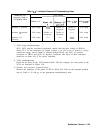
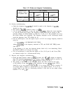
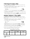
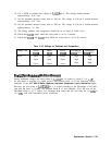
19. The analog switches and comparators should be set as listed in Table 11-16.
20. Check that U312D opens when the sweep time is set to 2 seconds.
21. Check that U312B and U312C close when the sweep time is set to 20 seconds.
Sweep Time
200 ms
2s
20 s
Table 11-16. Settings for Switches and Comparators
Switch
Switch Switch
Comparator
Comparator
U312B
U312C U312D U319A
Pin 1
U319B
Pin 7
Open Open
Closed High High
Open
Open
Open
High High
Closed
Closed
Open
High High
First
LO
Span
Problems
(Multiband
Sweeps)
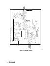
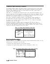
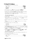
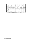
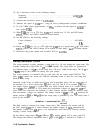
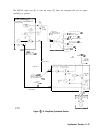
During multiband sweeps, the sweep ramp at A14J15 pin 15 should go from 0 V to
+lO
V
for each band or portions of a band covered. See function block A of Al4 frequency control
schematic in the HP 8560 E-Series Spectrum Analyzers Component Level Information binder.
However, the scan ramp at A14U325A pin 1 is scaled according to the percentage of the total
span that the band is covering. See function block B of Al4 schematic. Also, the sum of the
individual ramps is 10 V. Figure 11-9 illustrates both sweep and the scan ramp for a 0 GHz to
13.2 GHz span with instrument preset conditions.
Synthesizer Section 11-41