


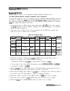
Flatness Control (RF Gain
DACs)
Refer to function block M of A3 Interface Assembly Schematic Diagram in the
HP 8560 E-Series Spectrum Analyzer Component Level Information.
RF Gain DACs control the Al5 assembly flatness compensation amplifiers. The RF Gain
DACs are arranged so that the output of one DAC is the voltage reference for the other DAC.
This results in an RF GAIN voltage which is exponentially proportional to the DAC settings.
Each DAC is set to the same value. The Al5 RF assembly converts the RF GAIN signal to
a current for driving the PIN diode attenuators in the Flatness Compensation Amplifiers.
The exponentially-varying voltage compensates for the nonlinear resistance-versus-current
characteristic of the PIN diodes.
1.
2.
3.
4.
5.
6.
7.
8.
Place the WR PROT/WR ENA jumper on the A2 controller assembly in the WR ENA
position.
Press
(CAL),
MERE
1
OF 2 , SERVICE CAL DATA , FLATNESS,
and
FLATNESS DATA . Press
NEXT
B$1BD
until “FLATNESS BAND #
0”
is displayed.
Press the
(Ir)
key until “DATA
@
300 MHz” is displayed. Note the number directly below
“DATA
@
300 MHz”; this is the RF Gain DAC value.
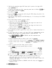
Connect a positive DVM lead to A3J400 pin 13 and the negative DVM lead to
A3TP4.
Check that the DVM reading increases from near 0 Vdc to between -1.3 and
-L.9
Vdc as
the RF Gain DAC setting is increased from 0 to 4095.
If the DVM readings are incorrect, press
(-1,
(SGLSWP],
(CAL),
MORE
I
OF
2 ,
SERYICE
CAL DATA, FLATNESS,
and
FLATNESS DATA.
Press
BUILT
BBPBp
until
“FLATNESS BAND #
0”
is displayed. Press the [Irl key until “DATA
8
300 MHz” is
displayed. Proceed as follows:
a. Check the
+lO
V reference.
b. Check for narrow, low-going pulses at A3U417 pin 13 (LWRCLK).
c. While rotating the front-panel knob, check for narrow, low-going pulses at A3U417 pin 1
(LDACl)
and pin 14
(LDACUI).
d. While rotating the front-panel knob, check for narrow, low-going pulses at U417 pin 16
(L-IAO) and pin 15 (IA4).
If the LWRCLK,
LDACl,
or
LDACUl
is incorrect, refer to the Interface Strobe Select
block in this chapter.
Place the WR
PROT/
WR ENA jumper on the A2 controller assembly in the WR PROT
position. Press [PRESET).
ADC/lntefface
Section 8-13