


Conditions
Menu
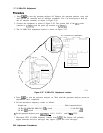
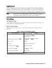
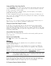
The first menu screen displayed is the Conditions Menu. The pointer displayed along the left
edge of the screen may be moved with the knob (if one is present) or the up (fi) and down
(4)
arrow keys. Notice that the menu has two pages. Moving the pointer below the last entry on
the page brings up the next page. Similarly, moving the pointer above the first entry on a
subsequent page brings up the preceding page.
Test Record Header Information
The information in the first six entries of this menu is for the user’s information only; it is not
printed or saved with any data. The spectrum analyzer model number and serial number are
stored in the analyzer memory. The program queries these numbers via HP-IB and displays
them. If the spectrum analyzer under test does not respond at the address listed under HP-IB
Addresses, or no address is listed, a message appears where the model and serial numbers are
normally displayed.
The program also queries the time and date in the computer. If an HP 9000 Series 200
computer is used, it might be necessary to reset the time and date; HP 9000 Series 300
computers have built-in real-time clocks.
Entries for Operator, Test Conditions, and Other Comments are optional. To make or to
change an entry, move the pointer to the line where the entry is to be made or changed. Press
Change
Entxy
and type in your new entry. Entries for Operator, Test Conditions, and Other
Comments can be up to 37 characters long, but only the first 25 characters of the Operator
entry are printed on the test record.
System Mass Storage File Location
Calibration factor data for different power sensors and a customized set of conditions may be
stored on disk. The mass storage unit specifier (msus) for the disk containing this information
should be entered as the system mass storage file location. Refer to the BASIC Operating
Techniques Munuul for information on the syntax of the msus. The software allows a system
mass storage file location with more than 37 characters though only the first and last 17
characters will be displayed.
The frequency response adjustment program disk comes write-protected from the factory.
If you want to use this disk for storing your power sensor and conditions data files, it is
necessary to disable the write-protect mechanism.
Note
A double-sided disk drive must be used. The frequency response adjustment
software will not fit on a single-sided formatted disk.
Power Sensors
The frequency response adjustment program supports two models of power sensors, but only
one model is necessary to run all the tests. The HP
8481A
is the preferred sensor. The
HP 8485A may be substituted if it has calibration factor data from 10 MHz to at least
18 GHz (the HP 8485A comes standard with data down to only 50 MHz). Refer to “Sensor
Utilities” for more information regarding storing, viewing, editing, and purging cal factor data
for power sensors.
3-6 Frequency Response Adjustment Software