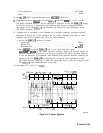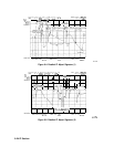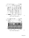
The center frequency of the 300 Hz resolution-bandwidth filters and the 1 Hz to 100 Hz filters
should differ no more than 10 Hz. If the center frequency is different by more than this, or
if no signal is present in the 1 Hz to 100 Hz resolution-bandwidth settings, troubleshoot the
10.6952 MHz VCXO.
Error message ERR 539 may occur if the VCXO is not oscillating. If problems exist with the
VCXO control voltage, error messages
ERR 536
or
ERR 530
may occur.
Between sweeps the VCXO, at times, is turned off. To prevent the oscillator from turning off,
press
(ii],
(FRE9UENCY),
0.3
(GHz),
ISPAN),
1
m),
(mSWP),
a),
and IF
&iU
OFF .
Input
Switch
Refer to function block D of A4 Log Amplifier Schematic Diagram (sheet 2 of 4) in the
HP 8560 E-Series Spectrum Analyzer Component Level Information.
The input switch switches between log and linear modes. In addition it contains a 20 dB
attenuator which is used only in digital resolution bandwidth settings. CR207, CR208, and
CR209 form the input switch. CR205 and CR206 switch in R234 when in linear mode to
maintain a constant impedance at J3. CR210, CR211, CR212, and CR221 switch the 20 dB
attenuator in and out.
LO
Switch
Refer to function block F of A4 Log Amplifier Schematic Diagram (sheet 2 of 4) in the
HP 8560 E-Series Spectrum Analyzer Component Level Information.
The LO switch switches the limiter input between the 10.7 MHz path or the 10.6952 MHz
VCXO path.
Synchronous
Detector
A wide dynamic range linear detector is realized by the limiter (block G), the isolation
amplifier (block H), the LO amplifier (block I),
and the detector/mixer (block J). The
combination of these circuits form what is commonly known as a synchronous detector.
The input signal is split between two paths. One path flows through the isolation amplifier
and the other path flows through the limiter and LO amplifier The path flowing through
the limiter generates the LO for the detector/mixer block. The path through the isolation
amplifier drives the RF port.
To troubleshoot this group of circuits set the RBW to 300 kHz. Inject 10.7 MHz at
+6
dbm
into J3. Probe the gate of A4Q404 or A4Q405 with a scope. Look for a 0 to -3 V square
wave. Decrease the input power from i-6
dBm
to -84
dBm
in 10 dB steps. The square wave
signal should remain unchanged. It is normal for the phase of the signal to jitter at the lowest
signal levels.
The signals at the gates of A4Q404 and A4Q405 should be 180 degrees out of phase from
each other. If they are not 180 degrees out of phase or one of the signals are not present,
troubleshoot the LO Amplifier or the
FETs
in the mixer. If the signal is not a symmetrical
square wave, troubleshoot the LO amplifier. If the signal drops out prematurely or is not
present at all, troubleshoot the limiter or LO amplifier.
Repeat the procedure for an RBW
5
100 kHz. If the log amplifier works in the 300 kHz RBW
but not in the narrower
RBWs,
troubleshoot the log narrow filter in the limiter or isolation
IF Section 9-19


