


10. Set a microwave source to the following settings:
Frequency . . . . . . . . . . . . . . . . . . . . . . . . . . . . . . . . . . . . . . . . . . . . . . . . .
4.2107GHz
Amplitude . . . . . . . . . . . . . . . . . . . . . . . . . . . . . . . . . . . . . . . . . . . . . . . . . . . . -5dBm
11. Connect the microwave source to A15UlOOJl.
12. Measure the signal at
U103
pin 1 using an active probe/spectrum analyzer combination,
13. If a 94.7 MHz signal, approximately -14
dBm,
is present, but the signal at
A15JlOl
is
low, suspect
U103.
14. When
U104
pin 3 is at TTL low,
U104
pin 6 should near -15 Vdc and PIN diodes
CRlOl,
CR102, and CR103 should be reverse-biased.
15. Set HP 85633 to the following settings:
Center frequency . . . . . . . . . . . . . . . . . . . . . . . . . . . . . . . . . . . , . . . . . . . . . 89.3 MHz
Span . . . . . . . . . . . . . . . . . . . . . . . . . . . . . . . . . . . . . . . . . . . . . . . . . . . . . . . . . . . . OHz
16. Check that
U104
pin 3 is at a TTL high and
U104
pin 6 is greater than
+7
V. PIN diodes
CRlOl,
CR102, and CR103 should all be turned on with about 7
mA
of forward current.
17. Disconnect the power splitter and reconnect W32 to
A15JlOl.
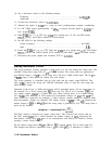
Sweep Generator Circuit
The sweep generator circuitry generates a ramp from 0 to 10 volts during the sweep time. The
available sweep times range from 50 ps to 2,000 seconds. The sweep times are generated in
two different ranges, a 50 ps to 30 ms range and a 50 ms to 2,000 second range. The 50
~LS
to
30
msec
range is only needed for analog zero span sweeps.
The sweep generator is controlled with an 8-bit latch and the control signal HSCAN. The
latch, U308, controls the sweep rate. HSCAN determines when to reset the scan ramp and
when to let it sweep.
Operation of the 50 ms to 2,000 second range will be described using a 50 ms sweep time as
the example. For a 50 ms sweep time,
Ql
shorts out C16. The D to A converter U307, has
zero output current. U334A is a buffer with zero offset, because there is no current coming
out of
U307.
The buffering of U334 makes the base-emitter voltages on Q3A and
Q3B
the
same. These two transistors are matched, so their collector currents should be identical when
their base-emitter voltages are identical. The emitter current of Q3B is 200
PA,
therefore the
emitter current of Q3A is 200
/.LA
and the sweep ramp is generated by C14. The sweep time is
given by the formula:
sweeptime = capacitance(C14)
cufrInt
The DAC setting is increased for longer sweep times. This increases the current sunk by
the DAC output
U307
pin 4, which increases the emitter voltage on
&3A,
decreasing the
base-emitter voltage drop. Q3A acts as an exponentiator and reduces its collector current,
creating a slower sweep ramp.
For the shorter sweep times, 50 ps to 30 ms,
Ql
is opened putting Cl6 in series with C14.
This changes the effective capacitance from 1
PF
to 1,000
pF,
or a reduction of 1,000 to 1.
11-46 Synthesizer Section