


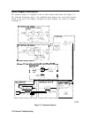
Digitally filtered video bandwidths use a sample detector. When sample detection is selected,
the effective video bandwidth is limited to approximately 450 kHz. When a digital filter is
selected, a D appears along the left edge of the CRT, indicating that something other than the
normal detector mode is being used.
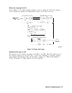
After filtering, the video is sent to the positive and negative peak detectors. These detectors
are designed for optimum pulse response. The positive peak detector resets at the end of
each horizontal “bucket” (there are 601 such buckets across the screen). The negative peak
detector resets at the end of every other bucket. When reset, the output of the peak detector
equals its input.
Triggering
The spectrum analyzer has five trigger modes: free run, single, external, video, and line. The
free run and single trigger signal comes from the 1 MHz ADC clock. The line trigger signal
comes from the A6 power supply. Video triggering originates from the A3 video filter buffer
circuit. External triggering requires either a high or low TTL logic level as determined by
the setting of the trigger polarity function. The external trigger signal is received from a
rear-panel BNC connector. A DAC in the trigger circuit sets the video trigger level. The
trigger circuit is responsible for setting HSCAN high.
Controller
Section
The controller section includes the A2 controller assembly and A19 HP-IB assembly. The A2
assembly controls the Al7 CRT driver through W7. The battery on the rear panel provides
battery-backup for state and trace storage.
The A2 contains the CPU, RAM, ROM, the display ASM and line generators, CRT blanking,
focus, intensity control, HP-IB interface, frequency counter, display RAM, option module
interface, and EEROM. The A19 HP-IB is a mechanical interface between the standard HP-IB
connector and the ribbon cable connector on the A2 controller assembly.
All six RAM ICs (four RAM ICs on 16 MHz controller assemblies) are battery-backed. The
battery-backed RAM stores trace information (two display memory RAMS) and spectrum
analyzer state information (two program RAMS). A total of eight traces and ten states
may be stored. Typical battery life is five years with the lithium battery. Trace and state
information may be retained for up to 30 minutes with a dead battery and power turned off.
This is due to the very low data retention current of the RAM.
EEROM
The EEROM stores important amplitude-related correction data. This includes data for
LO distribution amplifier DACs, preselector slope and offset DACs, RF gain DACs (flatness
correction), and preselector peak DAC. The spectrum analyzer serial number, model number,
and installed options are also stored in EEROM.
Firmware
The spectrum analyzer firmware reads the model number and installed options from the
EEROM to determine how to respond to certain keystrokes.
7-50 General Troubleshooting