


First
LO
Span
Problems
(All
Spans)
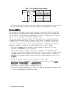
1. Set the spectrum analyzer to the following settings:
Center frequency
. . . . . . . . . . . . . . . . . . . . . . . . . . . . . . . . . . . . . . . . . . . .
..300MHz
Span
. . . . . . . . . . . . . . . . . . . . . . . . . . . . . . . . . . . . . . . . . . . . . . . . . . . . . . . . .
..2MHz
Resolution BW . . . . . . . . . . . . . . . . . . . . . . . . . . . . . . . . . . . . . . . . . . . . . . . . . . 1 MHz
VideoBW
. . . . . . . . . . . . . . . . . . . . . . . . . . . . . . . . . . . . . . . . . . . . . . . . . . . .
..lMHz
Sweep time
. . . . . . . . . . . . . . . . . . . . . . . . . . . . . . . . . . . . . . . . . . . . . . . . . . . . . 50ms
2. Check that there is 0 V to
+lO
V ramp of 50 ms duration at A14J15 pin 15.
3. If a scan ramp is not present, refer to “Sweep Generator” in this chapter.
4. If there is a 0 to -10 V ramp at A14J15 pin 14, the fault is probably in the Main/FM
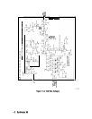
sweep switch. See function block H of Al4 frequency control schematic.
5. Check that there is a 0 V to
+lO
V ramp at U325 pin 1. The spectrum analyzer ADC
obtains information about the sweep from this node.
Check span attenuator (steps 6-13)
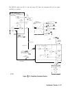
6. Continue with step 7 to check the span attenuator. See function block L of Al4 frequency
control schematic.
7. With the spectrum analyzer set to the settings in step 1, monitor A14U323 pin 6 with an
oscilloscope. A 0 V to -10 V ramp should be present.
8. Change the spectrum analyzer span to 1 MHz and check for a 0 V to -5 V ramp at U323
pin 6.
9. Change the spectrum analyzer span to 400 kHz and check for a 0 V to -2 V ramp at
U323 pin 6.
10. Set the spectrum analyzer to the following settings:
Start frequency . . . . . . . . . . . . . . . . . . . . . . . . . . . . . . . . . . . . . . . . . . . . . . . ..lO MHz
Stopfrequency
. . . . . . . . . . . . . . . . . . . . . . . . . . . . . . . . . . . . . . . . . . . . . . . .
2.9GHz
Sweep time
. . . . . . . . . . . . . . . . . . . . . . . . . . . . . . . . . . . . . . . . . . . . . . . . . . . . . 80ms
11. Monitor A14J15 pin 14 for a 0 V to -7.5 V ramp. Switches U317A, U317B, and U317D
should be open and U317C should be closed.
12. Change the spectrum analyzer SPAN to 365 MHz and check for a 0 mv to -1.0 V ramp at
A14J15 pin 14. Switch U317C should be open and U317B closed.
13. Change the spectrum analyzer SPAN to 36.5 MHz and check for a 0
mV
to -100 mV
ramp at A14J15 pin 14. Switch U317B should be open and U317A closed.
Check current source (steps 14-21)
14. Check the sweep generator current source with the following steps (function block A of
Al4 frequency control schematic).
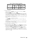
15. Set the spectrum analyzer to the following settings:
Center frequency
. . . . . . . . . . . . . . . . . . . . . . . . . . . . . . . . . . . . . . . . . . . .
..300MHz
Span
. . . . . . . . . . . . . . . . . . . . . . . . . . . . . . . . . . . . . . . . . . . . . . . . . . . . . . . . .
..lMHz
Sweeptime
. . . . . . . . . . . . . . . . . . . . . . . . . . . . . . . . . . . . . . . . . . . . . . . . . . . . . 50ms
1
l-40
Synthesizer Section