


5. DC Log Amplifier Adjustments
Equipment
Frequency synthesizer . . . . . . . . . . . . . . . . . . . . . . . . . . . . . . . . . . . . . . . . . . . . HP 3335A
Adapters
Type N (m) to BNC (f) . . . . . . . . . . . . . . . . . . . . . . . . . . . . . . . . . . . . . . . . . . . 1250-1476
Cables
BNC,122cm(48in)
. . . . . . . . . . . . . . . . . . . . . . . . . . . . . . . . . . . . . . . . . . . HP 10503A
Test cable
. . . . . . . . . . . . . . . . . . . . . . . . . . . . . . . . . . . . . . . . . . . . . . . . . . ...85680-60093
A5 IF
A4 LOG AMP/CAL OSC
J4
J3'
R445
JIO
(REVISION
CONNECTOR)
Jll
J9
J7
R826
J2
J8
J5
Jl
J4
R544
J3
R531-
sjlle
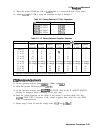
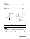
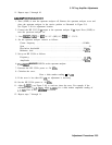
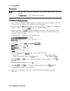
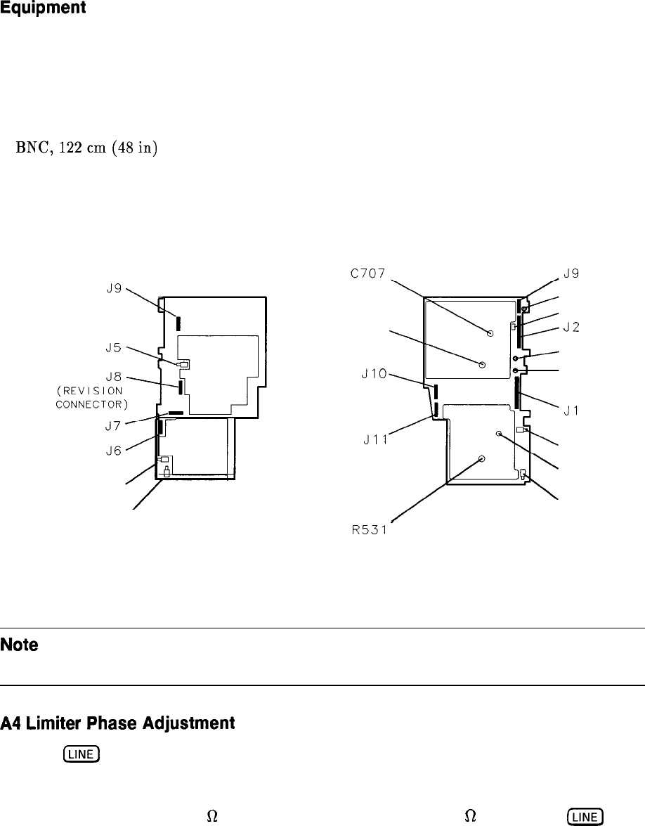
Figure 2-10. DC Log Adjustment Locations
Note
Adjustments should be made with all of the shields on and only after allowing
at least a 20 minute warmup.
A4
Limiter
Phase
Adjustment
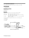
1. Press
(LINE]
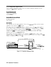
to turn the spectrum analyzer off. Remove the spectrum analyzer cover
and place the spectrum analyzer in the service position as illustrated in Figure 2-9. See
Figure 2-10 for adjustment location.
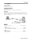
2. Connect the HP 3335A 50
R
output to the spectrum analyzer 50
Q
input. Press
ILINE)
to
turn the spectrum analyzer on.
Adjustment Procedures 2-31