


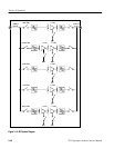

Theory of Operation
3-44
2715 Spectrum Analyzer Service Manual
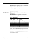
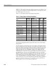
Table 3- 6: Mode Control Register 2 (Cont.)
Bit
Number
Description
Activity
Level
Mnemonic
4 MKRWFM0 Low Markers on Display A
3 UPDATED_L Low Display D updating, not in save mode
2 UPDATEC_L Low Display C updating, not in save mode
1 UPDATEB_L Low Display B updating, not in save mode
0 UPDATEA_L Low Display A updating, not in save mode
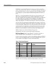
MKRWFM3. This bit, when low and the board is in the Normal Mode, enables
both markers to be displayed on the D waveform. When the board is in the
Enhanced Mode, this bit, when combined with the MKRWFM2 bit determines
on which waveform Marker 3 will be placed, as shown in Table 3--7.
MKRWFM2. This bit, when low and the board is in the Normal Mode, enables
both markers to be displayed on the C waveform. When the board is in the
Enhanced Mode, this bit, when combined with the MKRWFM3 bit determines
on which waveform Marker 2 will be placed, as shown in Table 3--7.
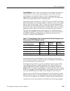
Table 3- 7:
Enhanced Mode MKRWFM[3..2] Bit Assignment
MKRWFM3
MKRWFM2 Marker 2 on Waveform...
0 0 Waveform A
0 1 Waveform B
1 0 Waveform C
1 1 Waveform D
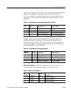
MKRWFM1. This bit, when low and the board is in the Normal Mode, enables
both markers to be displayed on the B waveform. When the board is in the
Enhanced Mode, this bit, when combined with the MKRWFM0 bit determines
on which waveform Marker 1 will be placed, as shown in Table 3--8.
MKRWFM0. This bit, when low and the board is in the Normal Mode, enables
both markers to be displayed on the A waveform. When the board is in the
Enhanced Mode, this bit, when combined with the MKRWFM1 bit determines
on which waveform Marker 0 will be placed, as shown in Table 3--8.