Maintenance
6-26
2715 Spectrum Analyzer Service Manual
Use the following procedure to replace the 1st LO Assembly:
NOTE. Replacement of this assembly requires completion of the. Amplitude
Flatness Adjustment Procedure on Page 5--52.
1. Remove the instrument from its cabinet (see Removing the Instrument from
its Cabinet on Page 6--17).
2. Remove the RF Deck from the Spectrum Analyzer (see Replacing the RF
Deck on Page 6--23).
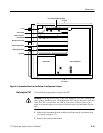
3. Disconnect P100 from the 1st LO Buffer Amplifier (semi rigid cable from
the 1st LO assembly to the 1st LO Buffer Amplifier).
4. Remove the 1st LO assembly from the RF deck.
Replace the 1st LO assembly by reversing the removal procedure.
Use the following procedure to replace the Step Attenuator:
NOTE. Replacement of this assembly requires completion of the. Amplitude
Flatness Adjustment Procedure on Page 5--52.
1. Remove the instrument from its cabinet (see Removing the Instrument from
its Cabinet on Page 6--17).
2. Disconnect P210 from the Step Attenuator. This is a multipin plug on the top
side of the RF Deck.
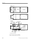
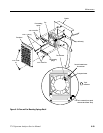
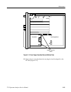
3. Disconnect P100, P200, and P150 (Figure 6--8 on Page 6--24) from the Step
Attenuator.
4. Remove the nuts and washers from J100, J150, J200, and J250 on the Step
Attenuator.
5. Remove the Step Attenuator.
Replace the Step Attenuator by reversing the removal procedure.
Replacing the 1
st
LO
Assembly
Replacing the Step
Attenuator


