


Theory of Operation
3-16
2715 Spectrum Analyzer Service Manual
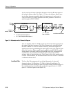
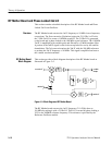
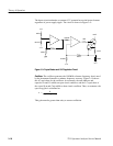
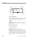
The directional coupler couples approximately --15 dBm of the amplified LO
signal to the detector. The coupled signal is then amplitude detected, and the
resultant DC level fed to the noninverting input of a comparator, where it is
compared to a reference DC level. (The reference DC level is connected to the
inverting input.) The output of the comparator then controls the active bias
tending to hold the amplifier’s output at a constant level.
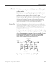
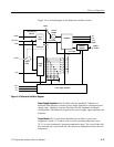
Strobe Driver. A Strobe signal from the Center Frequency Control assembly is
coupled to the Strobe Driver. The Strobe Driver is a transformer coupled gain
stage. The Strobe Driver’s output is coupled to the Sampling Gate.
Sampling Gate. A power divider at the input of the amplifier routes 50% of the
1st LO’s output to another power divider. One port of the second divider is
reserved for Option 15 and is terminated in 50 Ω. The other port is coupled to the
Sampling Gate.
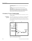
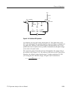
If the output frequency of the 1st LO were stable, LO sampling would occur at
the same level since the rate at which the LO output is sampled is constant.
However, the LO output has a tendency to drift slightly under certain conditions,
such as unstable ambient temperature. Consequently, sampling occurs at dif ferent
levels, resulting in a beat note. Thus, the BEAT NOTE signal is a measure of the
1st LO’s drift.
The output of the Sampling Gate is routed to the Phase Lock Center Frequency
Control (PLCFC) module.
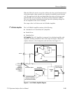
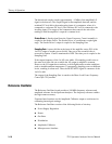
Reference Oscillator
The Reference Oscillator board provides a 100 MHz frequency reference and
amplitude reference for the Spectrum Analyzer. The frequency reference enables
the high counter accuracy.
Firmware based routines use the Amplitude Calibrator output as a reference for
calibrating internal gain settings.
The Reference Oscillator consists of the following blocks of circuitry:
H Power Supply Regulation
H Heater
H Oscillator
H Distribution
H Amplitude Calibrator
H Microprocessor Interface