


Theory of Operation
2715 Spectrum Analyzer Service Manual
3-77
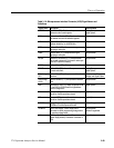
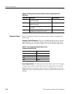
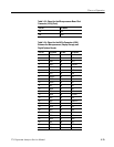
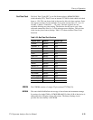
There are ten video gating control registers on the Digital Option module. All of
these control registers are write only registers, with the exception of misc. gating
control register (address 0x210). The other nine registers contain line count and
pixel count information used to control the IF gate and Display Storage
acquisition.
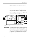
This system performs gating of the IF signal path at a point immediately before
the VR filter. It is composed of two components, the IF Gate itself and a control
signal conditioner.
This section performs the actual gating of 10 MHz IF signals. The desired action
is not to produce abrupt ON/OFF transitions like a switch, however, but rather to
perform controlled, rapid “fades” between ON and OFF. The intent is to
minimize the frequency domain sidelobes arising from the gating of any signals
present in the wide passband preceding the resolution filters. In the CATV test
environment the dominant signal present would most commonly be the visual
carrier of the channel under test, and we want to prevent the gating sidebands
from spoiling our ability to see weak distortion components near the visual
carrier frequency. The gate’s characteristics combined with those of the control
signal conditioner (see Control Signal Conditioner, next) define the transition
times and shapes.
In operation, 10 MHz IF signals entering J2 are converted to differential currents
at the collectors of Q3 and Q4. Note that the asymmetric arrangement of the
network in the emitters of Q3 and Q4 allows use of resistors instead of current
sources with little degradation of balance, taking advantage of the fact that the
base of Q4 is not driven with signal. The overall differential topology of the IF
gate is chosen to minimize even order distortion.
If IF_GATE_EN is held HIGH, Q7A and Q7D steer virtually all the differential
current from Q3 and Q4 through to the emitters of Q2 and Q13. Q2 and Q13
serve as common base stages to keep the large voltage swings at the input of the
transformer T1 off the collectors of Q7A and Q7D, which have large, nonlinear,
capacitances. This is to reduce distortion (particularly odd order terms) and to
improve the output circuit bandwidth.
If IF_GATE_EN is held LOW, the differential signal current is steered into Q1
and Q14 via Q7B and Q7C. The outputs of Q1 and Q14 are damped into
resistors R 1 and R 2.
During transitions, which are governed by the linear ramp waveform applied to
the bases of Q7B and Q7C, the differential signal current steered to the output is
modulated according to the transfer function of a bipolar transistor differential
amplifier having no emitter degeneration. The resulting soft envelope rise and
fall shapes provide a rapid fall off of sidebands with frequency offset from the
visual carrier.
Video Gating Control
Register
IF Gate System
IF Gate Proper