Theory of Operation
2715 Spectrum Analyzer Service Manual
3-33
A0, A1, and A2. Address lines for DAC internal register selection and control.
UPD. Used for simultaneous transfer to DAC output registers.
DB0’,dB1’,dB2’, and dB3’. Data lines for DAC U950 (A and B).
DB0, dB1, dB2, and dB3. Data lines for DAC U850 (A and B).
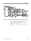
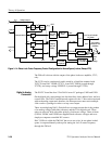
Variable Resolution Module
This section contains a detailed description of the Variable Resolution module.
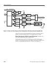
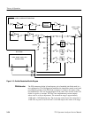
The input amplifier used is a transformer feedback stage that provides approxi-
mately 12 dB of gain with 10 dB of reverse isolation. See Figure 3--15. The
match at each port with the other terminated is better than 15 dB at 10 MHz. The
noise figure is less than 3 dB and, with 12 mA flowing in the device, the output
intercept is approximately +30 dBm. The match at each port is highly sensitive
to a proper termination being presented to the other port.
Input Amplifier


