Theory of Operation
3-24
2715 Spectrum Analyzer Service Manual
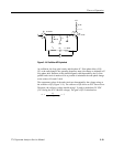
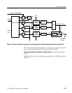
This voltage across R926 defines the feedback current to the summing junction
of the operational amplifier. This circuit forces 1st LO main coil current to be
proportional to the sum of the currents from the various control sources, which is
described later. The normal operating current range of the main coil is from
approximately 135 mA to 255 mA.
Q920 is a switch that is normally conducting and consequently has no significant
impact on circuit operation as described. However, it is sometimes necessary to
momentarily set the main coil current to zero in order to standardize frequency
errors due to hysteresis in the 1st LO magnetic structure. When this is desired,
the microprocessor asserts the DEGAUSS line HIGH (by way of the digital
interface circuits), which causes Q931 and Q930 to pull the gate of Q920 to
--8.5 V. This opens the switch, disconnecting the normal input and feedback
paths of the circuit. R929 provides a slight negative feedback in this situation,
ensuring that the main coil current goes to zero instead of to some undefined
value.
The main coil current is the sum of at least two items. First, there is a large fixed
bias current stemming from the reference supply and R923 (trimmed by R931
and U920) to set the 1st LO at 3.01 GHz in the absence of other inputs. Second,
there is a current induced by DAC U950A (and subsequent circuits), which is
used to steer the 1st LO over the range from 2.11 to 3.91 GHz (2.11 to 4.26 GHz
for Option 50 and Option 75). This current is normally a steady state value
selected by the microprocessor to coarsely set the center frequency. Third, if the
instrument is set to a span greater than 5 MHz/div, there is a sawtooth sweep
waveform summed into the main coil current through switch U830A. This
corresponds to the wide span operating mode discussed earlier in the Block
Diagram description.
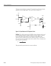
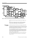
FM Coil Driver. U811 and U810 together form a buffered operational amplifier
used in the inverting configuration. Input currents to the summing junction come
from a variety of sources, to be described later. R905 is the current sense resistor
for the FM coil. The voltage developed across it results in the current fed back to
the summing junction through R815. Thus, this circuit forces a current through
the FM coil proportional to the sum of the various control currents put into the
summing junction. The normal current range for the FM coil is from approxi-
mately --120 mA to +120 mA.
Q910 and Q91 1 serve as a low resistance switch. When closed (gates held
several volts positive), the FM coil driver operates as described above. When
open (gates held several volts negative), the driver is disconnected and the FM
coil gets its current from R714, which is the situation when the instrument is
phase locked. Control of the switch state is through Q703 and Q800 from the
signal PLLCON--. This signal is LOW when the instrument is phase locked.
Several other switches are also controlled by the same command. R812 keeps
U811 out of saturation when the switch is open.


