Theory of Operation
2715 Spectrum Analyzer Service Manual
3-3
The Spectrum Analyzer accepts an electrical signal as its input and displays the
signal’s frequency components on a CRT. Signals are applied directly to the RF
INPUT.
The display of the input signal appears on the CRT as a graph where the
horizontal axis is frequency and the vertical axis is amplitude.
The Spectrum Analyzer operates as a variable bandwidth receiver. The CR T
beam moves horizontally as a range of frequencies is scanned. When a frequency
component of an input signal is detected, the beam is deflected vertically as a
function of input power at that frequency.
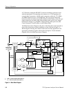
There are two selections for inputs to the Spectrum Analyzer: the RF INPUT at
the front panel and the internal calibrator signal.
The Attenuator adds attenuation to the input signal such that the level at the
input of the 1st mixer (1st Converter) is limited to no more than --30 dBm. This
would represent a full screen signal. Also, an amplifier can be inserted in the
signal path to improve sensitivity when small signals are applied to the RF
INPUT by invoking the Preamp mode. The Microprocessor sets the amount of
attenuation, depending on the user selected reference level, to maintain the
proper signal level.
The signal is then routed to the 1st Converter through a Low Pass Filter. The
Low Pass Filter attenuates out-of-band signals and helps minimize 1st Local
Oscillator (LO) emission at the RF INPUT. When the Preamp mode is invoked,
the Microprocessor sets the appropriate amount of attenuation, or it sets the gain
of an internal amplifier (Variable Resolution) to maintain a calibrated display.
The input signal is converted to an intermediate frequency (IF) signal of
2110 MHz. This is accomplished by mixing the input signal with an LO signal
that varies over a range of 2.11 GHz to 3.91 GHz (4.26 GHz for Option 50 and
Option 75). The LO range corresponds to a range of 0 Hz to 1.8 GHz (2.15 GHz
for Option 50 and Option 75) at the RF INPUT. The output of the mixer is then
amplified to compensate for the conversion loss, and it is filtered to allow only
the difference frequency to pass. All other mixer products are attenuated.
The 2nd Converter down converts the 2110 MHz IF signal to 110 MHz, then
routes this 2nd IF to the RF Mother board.
What It Does
How It Works
Attenuator and Low Pass
Filter
1
st
Converter and
Bandpass Filt er
2
nd
Converter


