


Theory of Operation
3-54
2715 Spectrum Analyzer Service Manual
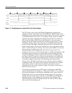
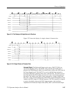
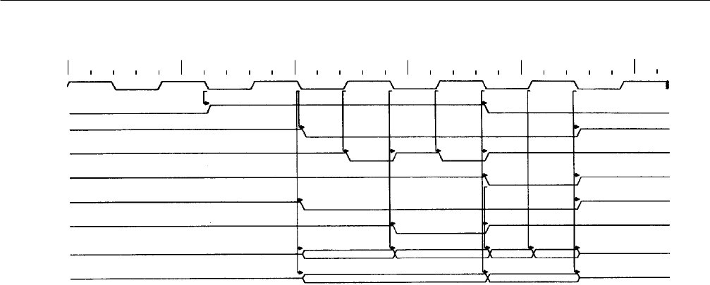
BCLK
BOB
ACQGRNT_L
WE_L
OE_L
CEO_L
0ns 500ns 1000ns 1500ns 2000ns 2500ns
CE1_L
RAMD<7. .0>
RAMAD<14..0>
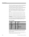
Figure 3- 19: Sequence of Events W hen Writing Data to the Waveform Memory
The two DS1210’s, U6 and U28, are used to provide battery backup power to the
RAM devices while the instrument is in the off state.
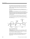
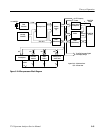
Readouts and Waveform Drawing. The Readouts and Waveform Drawing section
places all readouts and waveforms on the CRT screen. It does this using an
XC3042 LCA (U46), a CY7C 291 PROM (U48), two 22V10 PALs (U39 and
U40), a 74HCT541 buffer (U47), and three 74HCT257 quad 2--1 multiplexers
(U50, U51, and U52).
The easiest way to view the display section of this board to look at it as if each
waveform or screen of text were a page. There are eight pages, four pages of
waveforms (waveforms A through D) and four pages of text (one for readouts
and 3 more for menus). U39 and U40 form a state machine called the Readout
State Machine which is used to turn the CRT beam on and off, load data for
display from R AM, and determine which pages should be displayed. The
Readout State Machine begins by determining which page needs to be displayed,
starting with page 0. By taking the contents of the Display Control Register (U21
and U25) and comparing it to a 3 bit counter (Page Counter, internal to U46) it
can be determined which pages need to be displayed. For example if DISPA is
high and the page counter is at zero, then Waveform A should be displayed. This
comparison is performed in U40. Once U40 determines that a page should be
displayed, the Readout State Machine will then load the appropriate data and
display the page. Depending on whether the page to be displayed is text or
waveform, the Readout State Machine takes one of two paths.
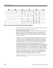
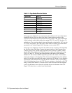
Table 3 --14 illustrates the relation between the page counter, page number and
the waveform or text page.