


Theory of Operation
2715 Spectrum Analyzer Service Manual
3-39
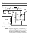
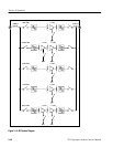
The core of the logging stage is a pair of AD640s. The AD640 uses five
cascaded limiting amplifiers to approximate a logarithmic response to an input
signal of wide dynamic range and wide bandwidth. The two AD640s are used in
a parallel/summing operation. The input signal to one AD640 is amplified by
25 dB with the CLC 501. This is a current feedback operational amplifier that has
a clamping circuit used to limit the output to a value set by an external voltage
divider. The other AD640 is fed through a 25 dB attenuator. The difference in
input amplitude for small signals is then 50 dB. There is not enough gain in the
75 dB path to cause the AD640 to limit on the input noise of the CLC501. Thus,
the full dynamic range of both parts is realized. This topology eliminates the
need for a narrow bandwidth noise filter.
In Lin mode, the signal envelope is extracted from the RF carrier by the use of a
synchronous detector. This detector is basically a multiplier. Detection is
accomplished by feeding a limited signal into one input and a sample of the RF
signal into the other. Since the limited input is always considered equal to plus or
minus one unit, only the polarity is important. The sample RF is then multiplied
by plus or minus one. Since the RF is always in phase with the limited input, the
product is always positive. Thus, demodulation is achieved.
The ripple filter is a six pole elliptic filter with a finite transmission zero at the
10 MHz IF frequency and another at approximately 19 MHz. The purpose is to
remove any of the remaining 10 MHz component that may still exist. Because of
the full wave rectification provided by the synchronous detector and the log
cells, the 10 MHz component is attenuated by approximately 30 dB. This greatly
reduces the requirements of the ripple filter. However, the signal is not always at
10 MHz. The widest bandwidth is 5 MHz, so there is still a significant require-
ment for ripple reduction as low as 5 MHz.
After the Ripple Filter, the signal is offset before being amplified to bring the
equivalent of a full screen signal in log mode or linear mode to correspond to
0 V output. The out-of-band clamp is also done at this time to deflect the CRT
beam into the bottom of the screen when the display is outside the frequency
limits of the Spectrum Analyzer. Next, the video filter selector is chosen. The
bandwidth of the vertical chain is approximately 5 MHz. Therefore, when a
video filter path is chosen, the maximum bandwidth drops to approximately
1 MHz. This switching tree also multiplexes in the external signals from the rear
panel or the FM Detector.
Logarithmic Amplifier
Stages
Synchronous Detector
Ripple Filter
Video Filter/Scale Factor