Adjustment Procedures
2715 Spectrum Analyzer Service Manual
5-17
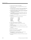
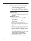
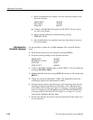
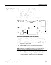
Use this procedure to adjust R931, R918, R920, R746, R827, R620, and C611
on the Phase Lock assembly.
H Test equipment required: Time Mark Generator
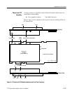
Refer to Figure 5--5 for adjustment and test point locations excluding TP168 on
the Sweep board.
J130 (YIG BEAT FREQUENCY)
J1
J240 (Count)
PHASE LOCK CFC Board
Phase Lock
Assembly
(LFVCO & HFVCO)
Feedthrough Test Point
J100 (STROBE)
C611
R918 R920 R827 R931
Bottom View
R746R620
Top View
J1
J1
Center
of R620
Figure 5- 5: Phase Lock CFC Module Adjustment and Test Point Locations
Phase Lock CFC
Assembly


