Theory of Operation
3-86
2715 Spectrum Analyzer Service Manual
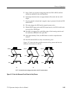
The three conditions illustrated in Figure 3--27 are as follows:
1. Switch pressed and released inside the 50 ms time of POS.
2. Switch pressed and released well after both the POS and ROS have timed
out.
3. Switch pressed and released with the POS becoming inactive during the
release.
The debounce single shot is triggered by the rising edge of the POS and has a
1 ms pulse width. At the end of the 1 ms pulse, the following two conditions
occur:
H The status of the switch matrix is stored in the output shift registers (U130,
U140, and U319).
H The service request circuit on the Front Panel board is activated.
The gray code knob is a rotary knob that outputs a two bit gray coded pulse train.
The direction of the knob is decoded by monitoring the two output lines of the
knob. The two knob outputs drive a NAND gate whose output is used to trigger
a single shot. The single shot is positive edge triggered. Triggering the single
shot in this method gives a pulse to the Service Request/Acknowledge circuit as
the knob leaves the position of both bits high. The direction of the knob can be
determined by loading the status of the knob just after the both bits high
position.
Two open collector transistors on the knob outputs are used to set the correct
TTL levels. In addition, two Schmitt trigger inverters are used to buffer the
transistor outputs and speed up the edge transitions.
The Service Request/Acknowledge circuitry consists of two flip flops (request
for service flip flop) that request service from the firmware. A description of a
typical request for service and firmware acknowledgment follows:
1. A key is pressed on the front panel and the output of the Press One Shot goes
high.
2. The rising edge on the Press One Shot output triggers the debounce single
shot. The falling edge of this pulse loads the switch matrix status and clocks
the first flip flop.
3. The output of the first flip flop then sets the request for service flip flop,
making the FPREQ signal low (active).
4. The output of the request for service flip flop is then used to reset the load
flip flop, thus completing a load pulse for the shift registers.
Gray Code Knob
Service
Request/Acknowledge
Circuit


