Adjustment Procedures
5-62
2715 Spectrum Analyzer Service Manual
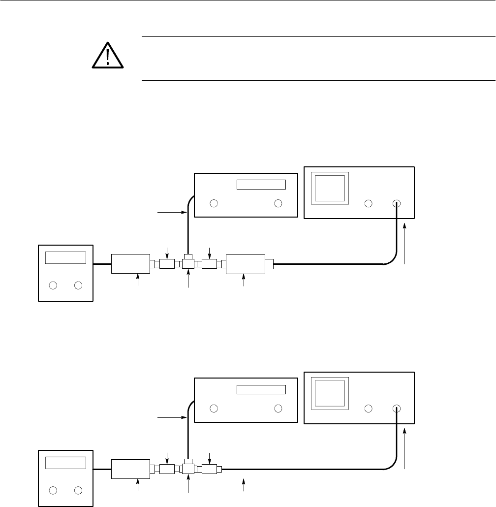
CAUTION. Provide adequate support for the power divider and related equip-
ment. The RF INPUT connector of the 2715 can be damaged if adequate support
is not provided.
The test will require about 2
3
⁄4 hours to complete. At the completion of the test,
the measurement data will be downloaded to the 2715. Data will not be
downloaded if the test failed.
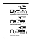
Power Meter
50 Ω Cable
Min Loss Pad50 Ω Power
Sensor
Power
Divider
6dB
Pad (N)
20 dB
Pad (N)
Connects Directly to RF INPUT
of Instrument Being Tested
2715 Spectrum Analyzer
Signal Generator
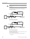
Figure 5- 28: Flatness Test Setup (75 Ω)
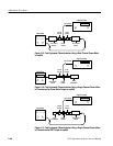
Power Meter
50 Ω Cable
Min Loss Pad50 Ω Power
Sensor
Power
Divider
6dB
Pad (N)
20 dB
Pad (N)
Connects Directly to RF INPUT
of Instrument Being Tested
2715 Spectrum Analyzer
Signal Generator
Figure 5- 29: Flatness Test Setup (50 Ω)
Run the Flatness Verification Program. This section checks the flatness correction
of the 2715 generated in the previous step.
Type the following on the personal computer to run the 271X program.
271X<Return>


