


Performance Verification
4-12
2715 Spectrum Analyzer Service Manual
6. Set the Vertical Scale to 5 dB/.
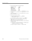
7. Set the attenuators for 0 dB and adjust the signal generator amplitude for full
screen display.
8. Increase the attenuation 5 dB and check that the Marker readout changes
5dB±1dB.
9. Continue to increase the attenuation in 5 dB steps to a total attenuation of
40 dB while checking the Marker readout for a change of 5 dB ±1dB.
Check that the Marker readout change for each 10 dB change does not
exceed ±1 dB or that the cumulative error does not exceed ±2 dB over the
40 dB range.
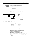
10. Set the Vertical Scale to 1 dB/.
11. Set the attenuators for 0 dB and adjust the signal generator amplitude for full
screen display.
12. Increase the attenuation 1 dB and check that the Marker readout changes
1dB±1dB.
13. Continue to increase the attenuation in 1 dB steps to a total attenuation of
8 dB while checking the Marker readout for a change of 1 dB ±1 dB at each
step. The specification is ±1 dB per step over the 8 dB range.
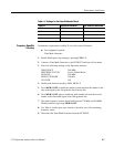
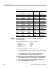
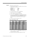
14. Set the Resolution Bandwidth and Span/Div as indicated in Table 4--6 and
repeat steps 3 through 13 for each Resolution Bandwidth filter.
Table 4- 6: Resolution Bandwidth Filter Display
Dynamic Range Settings
RES BW SPAN/DIV
300 Hz 1 kHz
1 kHz 5 kHz
3 kHz 10 kHz
10 kHz 50 kHz
30 kHz 100 kHz
100 kHz 500 kHz
300 kHz 1MHz
1MHz 10 MHz
5MHz 20 MHz
15. After completing the above procedure, disconnect the signal generator from
the RF INPUT.