


Theory of Operation
2715 Spectrum Analyzer Service Manual
3-7
1
st
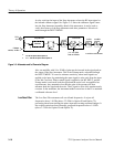
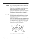
LO Buffer
The 1st LO Buffer consists of a Leveled Amplifier and a Phase Gate Detector.
The Leveled Amplifier provides the LO input drive for the 1st Mixer. The Phase
Gate Detector logs 1st LO drift. That information is then used for frequency
corrections.
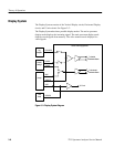
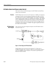
Sweep
The Sweep board contains a microprocessor interface, horizontal sweep
generator, trigger circuitry, vertical sweep (raster scan) circuitry, video proces-
sing, video line triggering, and graticule illumination.
This board receives messages from the microprocessor regarding its operation,
but cannot send messages directly to the microprocessor.
Various combinations of resistors and capacitors yield the sweep speed selec-
tions.
The available trigger modes are Free Run, Internal, Line, External, TV Field, and
TV Line. When the video monitor mode is selected, the readout, display storage,
and video filter are turned off. In addition, the resolution bandwidth is set to
5 MHz, the Vertical display mode defaults to Lin, the span setting defaults to
Zero Span, and the sweep rate defaults to 5 s. The video monitor mode is
turned off from the trigger menu or by selecting another trigger mode.
TV Line Trigger mode causes the Spectrum Analyzer to trigger on the selected
video line. The selected line, and part of the next line, are displayed.