Theory of Operation
3-68
2715 Spectrum Analyzer Service Manual
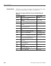
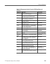
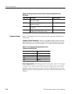
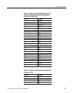
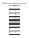
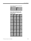
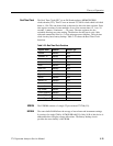
The Microprocessor requires several signals. A brief description of these signals,
by connector, is given in Table 3--18, Table 3--19, and Table 3--20.
Table 3- 18: Power Supply and Serial Bus Connector (J10) Signal Names and
Definitions
Signal Name Description Source Module
DETVID Detected Video: The demodulated AM or FM
signal from the Log Board
Log Board
SWPGATE Sweep Gate (TTL): Signal that is active during
the sweep
Display Storage
POK Power OK: Tells CPU that the +5 V supply is OK Power Supply Secondaries
REQI-- Request Interrupt (TTL): I/O Subsystem request
for service
Power Supply Secondaries
UPAUD Microprocessor Audio: Square wave output at
frequency of the audio tone
Microprocessor
CLKI-- Clock I n (TTL): Microprocessor Serial bus input
clock
Microprocessor
CLKO Clock Out (TTL): Serial bus output clock Microprocessor
DATAI Data In (TTL): Serial bus data in Rear Connector, RF Op-
tions, Front Panel, PLCFC
DATAO Data Out (TTL): Microprocessor Serial bus data
out
Microprocessor
ACKI-- Acknowledge Interrupt (TTL): Enables priority
encoder on Power Supply Secondaries
Microprocessor
LOAD-- Load (TTL): Latches data into receiving module
on serial bus
Microprocessor
ADI0 through
ADI2
Address In (TTL): Address of module on serial
bus requesting service
Power Supply Secondaries
ADO0 through
ADO2
Address Out (TTL): Address of receiving module
on serial bus
Microprocessor
SSTRIG Single Sweep Trigger (TTL): Triggers a si ngle
sweep on the Sweep board
Microprocessor
+5 V +5 V: +5 V digital supply Power Supply
Hardware Interface


