Adjustment Procedures
2715 Spectrum Analyzer Service Manual
5-45
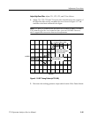
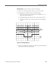
Adjust High Pass Filter. Adjust C21, C22, C23, and C24 as follows:
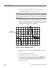
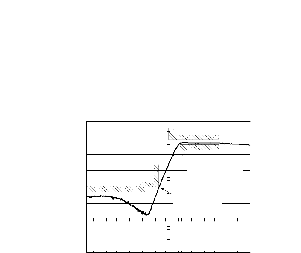
1. Adjust C21, C22, C23 and C24 on the video demod board so the response of
the High Pass filter closely resembles the curve shown in Figure 5-- 17 and
conforms to the limits indicated in the figure.
NOTE. C21 and C 22 primarily tune the notch seen at about 93 MHz; C23 and
C24 primarily affect the area around the knee seen near 103 MHz. However,
there is appreciable interaction between the adjustments.
10 dB/DIV
5 MHz/DIV
At least 40 dB insertion
loss at 97.0 MHz
No more than 14 dB
insertion loss in passband
103.5 thru 115 MHz
At least 11 dB insertion loss
in range 100 thru 115 MHz
Figure 5- 17: HPF Tuning Criteria (at TP110M)
2. Disconnect the tracking generator output cable from the Video Demod board.


