Theory of Operation
3-58
2715 Spectrum Analyzer Service Manual
Offset, (HOO) R98, are provided. In addition part of U34, an analog switch, and
another resistor are added in parallel to the feedback resistor of the operational
amplifier to allow gain reduction while the readouts are being drawn. This will
allow the waveform to extend beyond the edge of the graticule and still allow the
readouts to be visible.
There are also two analog switches which are used to multiplex between the
digitized information (HORIZ signal) and the analog trace (SWP signal) during real
time displays.
Vertical Output. The Vertical Output Section converts the vertical data from the
Readout LCA (U46), into the DSVER signal, which is then used to deflect the CRT
beam by the Power Supply. There are two paths through the Vertical Output Section.
A high bandwidth path for the readouts and an integrator path for drawing the
waveform vectors. Both the waveform and readout paths will be described in the
following paragraphs.
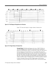
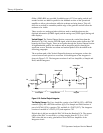
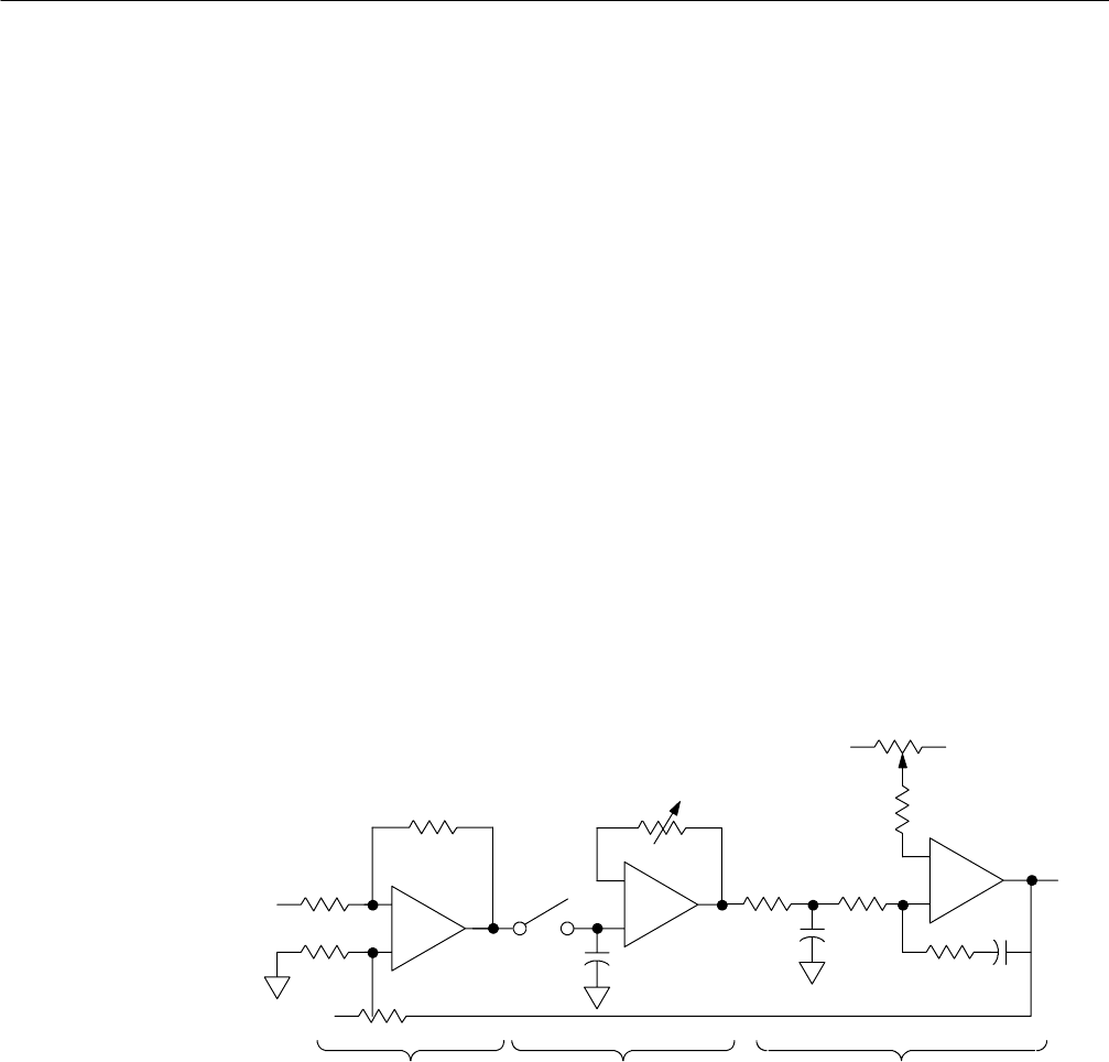
The waveform path of the Ve rtical Output Section uses an integrator to draw the
vectors between each point in a waveform. A block diagram of the integrator is
shown in Figure 3--23. The integrator consists of an Error Amplifier, a Sample and
Hold, and the Integrator.
Vector Length
Vector Offset
--
+
--
+
Error Amplifier Sample and Hold Integrator
+
--
Vout
+VR-- V R
Vin
Figure 3- 23: Vertical Output Integrator
The Display Storage. The Error Amplifier consists of an LM318 (U53), a BT3904
transistor (Q4), and a BT3906 transistor (Q5). The Sample and Hold consists of
part of a DC641 (U34), capacitor C94, and half of a TL072 (U57). The integrator
consists of one half of a TL072 (U57) and capacitor C93.
Digital data is fed into an eight bit DAC--08 from the Readout LCA. The current
output of the DAC is converted to a voltage ranging from 0.170 V to 1.30 V.
This is then fed into a unity gain buffer to drive the Error Amplifier of the
Integrator circuit.


