Adjustment Procedures
5-24
2715 Spectrum Analyzer Service Manual
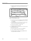
aa. Adjust R501 on the Log board to position the trace at the third graticule
line from the top of the screen.
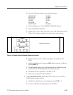
ab. Insert an additional 40 dB of attenuation in the input signal path.
ac. Adjust R770 on the Log board to position the trace at the seventh
graticule line from the top of the screen.
ad. Repeat steps z through ac to compensate for interaction between the
adjustments of R501 and R770.
3. Check Logging as follows:
a. Remove all attenuation from the input signal path. (Set the external
attenuators for 0 dB.)
b. Insert a total of 80 dB of attenuation in the input signal path in 10 dB
steps.
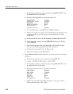
c. For each 10 dB step, check that the signal level falls within a 1/2 minor
division of a major graticule line over the first seven divisions as each
10 dB of attenuation is added, and within two minor divisions of the
bottom graticule line for the 70 dB to 80 dB step.
d. Reset the external attenuators to 0 dB.
e. Reset the VERTICAL SCALE to 5 dB/div.
f. Insert a total of 40 dB of attenuation in the input signal path in 10 dB
steps.
g. Check that the signal level falls within one minor division of the --40 dB,
--50 dB, --60 dB, and --70 dB graticule positions as each 10 dB of
attenuation is added. The cumulative error over the 40 dB range should
not exceed two minor divisions (2 dB).
h. Reset the external attenuators to 0 dB.
i. Reset the VERT SCALE to 1 dB/div.
j. Insert a total of 8 dB of attenuation in the input signal path.
k. Check that the signal level falls within one major division of the bottom
graticule line.
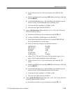
4. Adjust Linear (LIN) Mod (R431, R500, and R526 on the Log board) as follows:
a. Disconnect the 10 MHz signal from J190 on the Log board.
b. Reset the VERT SCALE to LIN.
c. Monitor TP9 on the Log board with the multimeter.


